Now a days, those computer supplies are very cheap.
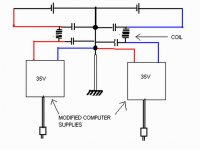
I was thinking if is possible to modify to 35 Volts for instance.
Do you think that the oscilating frequency will be captured by our audio amplifiers?
Do you think we can increase the oscilating frequencies to avoid that?
The increase of oscilating frequency will be a good solution?
Can this frequency cross the Supply shield can and be detected by our amplifiers?
Do you think that I can install 30000 uF in the outputs?
Can you suggest modifications to use them as audio supplies?
Do you have some experience?… something practical related that?
Can you suggest filter values?
Do you think that I will maintain the supply power when increase the voltage….. as 240 watts can be 20 amperes and 12volts….will 35 Volts have more than 6 amperes as simple calculations will shown us?
If you can answer to one of more questions, please, go ahead.
Thank you in advance by the cooperation
Regards,
Carlos
Attachments
I have already made some modification to use as a Radio Amateur, 13.8 Volts - 16 amps
But i made it using an sketch...was not my idea, i do not understand those switching supplies very well.
I remember that i gave it to a friend, as it produces some carrier beating with my receptions...alike a frequency marker.....do not remember exactly, but i think was 30 or 40 Kilohertz the carrier generated by that supply.
regards,
Carlos
Attachments
Worst than that, i suppose that 2 supplies will create two signals to beat .
those signals beating one with the other will produce a big mess....well, i do not know...reason i am asking you guys.
I am sure, even with small knowledge, you may be better than i am related those supplies...i do not understand nothing about them...i have an idea of the operational work only.
regards,
Carlos
Attachments

I would be carefull with an LC filter on the output.
SMPSs sometimes have problems when the load turns complex and the regulation loop can become unstable.
If you want to risk it you can try an LC filter, but you might end up with a more dirty supply that you had before.
\Jens
SMPSs sometimes have problems when the load turns complex and the regulation loop can become unstable.
If you want to risk it you can try an LC filter, but you might end up with a more dirty supply that you had before.
\Jens
Thank you Jens, i was suspecting that this may have problems, as not normally used.
And of course, a lot of guys already had this idea before me.
I will be satisfied knowing the reasons, as the price is very atractive, calling my attention for that.
Used ones can be bougth at a ratio of 3 units for one dollar.... really interesting, even beeing 10 years old supplies.
thank you by the cooperation,
regards,
Carlos
LC filters in the output of a SMPS are fine as long as they are damped. Only filters with considerable resonance peaks will cause trouble.
By the way, those PSUs may be modified for 35V or even +-35V output, but that will require to rewind the transformer, new output rectifiers and to redraw the secondary side of the PCB.
I have been tempted sometimes to develop some easy to build SMPS with symmetrical outputs in the 500W range (where computer PSU parts and cases could be employed), and publish the schematic, board layouts and all the data for DIY. But I don't know if it's worth the effort, and these circuits have to be built and tested with great care due to the mains isolation requirements, so it won't be suitable for everybody.
Eva said:LC filters in the output of a SMPS are fine as long as they are damped. Only filters with considerable resonance peaks will cause trouble.
You are correct, but I have seen both Buck/Boost and standard buck converters misbehave when a damped output LC filter was Deployed. I had to redesign the loop to compensate for this problem. The loop work is not always needed, but it is possible that it can be necessary when modding something.
You also have to carefully design the filter so that it infact works in the freq area where the noise is present, something that can be difficult without a scope/spectrum analyzer.
I think a modded PC supply could be a nice idea, but I would rather construct something from scratch...
Maybe next year
")
\Jens
Very intresting thread that you started Carlos.
Many times before i wondered haw this kind of psu can be modifide to use with audio amplifires since many of them can be find very cheap and easy.Many pepole just throw them to garbage and they work fine.
I dont know haw this psu works exactly to modifie them, but with some help from more experienced pepole over here i can do this i think.Something simple i wonder is haw can it be done to take of the fan.Will then some beter heatsinks be suitable to do the job? Although there are more serious things to modifie this is just a thought i have right now.
Thanks George
Good that you apreciated George, and also nice to have Jens and Eva
Those ones, Jens and Eva are good EE, and Eva is deeply experienced in those supplies....maybe Jens too.
Eva, if you have some sketch, may be interesting to publish, so we can try, if it is not too much complicated.
regards,
Carlos
Those ones, Jens and Eva are good EE, and Eva is deeply experienced in those supplies....maybe Jens too.
Eva, if you have some sketch, may be interesting to publish, so we can try, if it is not too much complicated.
regards,
Carlos
Hi carlos,
If you put a computer power supply to supply your amplifier you will have much noise, because this supplys isn't isolated from your AC-Line.
Frist,
You will change the frist diode bridge to a 8A Diode Bridge.
Second,
Change the dissipators. Because this isn't addecuated...
Third,
Put a Choke Coil in the input line and in the output line.
I think you isn't will have 35v. I have modified the line of 12v of a Enermax power supply ( It costs R$350 in Brazil ) to have in the output the high voltage to me.
The high voltage I have before the power supply will southdown ( is it correct? ) is 20v.
How you will give 35v from this power supply?
If a toroid is employed, you have to manage to put 3 layers of mylar insulation tape (or a material with similar properties) between the primary and the secondary windings. I have tried it and taping such a toroid ends up being quite difficult. Toroids are usually found in applications where no special insulation requirements exist.
Eva said:If a toroid is employed, you have to manage to put 3 layers of mylar insulation tape (or a material with similar properties) between the primary and the secondary windings. I have tried it and taping such a toroid ends up being quite difficult. Toroids are usually found in applications where no special insulation requirements exist.
Thanks for clearing that up.
Would not want a short to form (or a spark to jump) between primary and secondary windings!

destroyer X said:Now a days, those computer supplies are very cheap.
I was thinking if is possible to modify to 35 Volts for instance.
Do you think that the oscilating frequency will be captured by our audio amplifiers?
It very well could.
Do you think we can increase the oscilating frequencies to avoid that?
It'd probably end up more work than it's worth.
The increase of oscilating frequency will be a good solution?
Not in my opinion.
Can this frequency cross the Supply shield can and be detected by our amplifiers?
Yes.
Do you think that I can install 30000 uF in the outputs?
Likely no.
The current needed to charge those would likely cause damage.
Can you suggest modifications to use them as audio supplies?
I'd recommend avoiding them.
Do you have some experience?… something practical related that?
They're very noisy.
Can you suggest filter values?
No.
Do you think that I will maintain the supply power when increase the voltage….. as 240 watts can be 20 amperes and 12volts….will 35 Volts have more than 6 amperes as simple calculations will shown us?
It's not that simple
If you can answer to one of more questions, please, go ahead.
OK
Thank you in advance by the cooperation
Regards,
Carlos
I dig out some tips from an old radio telecommunications magazine.
It is a 13.6 V 20A psu made out of the Computer psu. All you need for added parts are a couple of 20 Watt 10 Ohm Power
Resistors, a FT140-43 Toroid Cors, a fuse holder and fuse.The 20 Watt 10 Ohm Resistors are to load the 5 Volt Supplies. The Computer Power Switchers will not produce output with out this load.The FT140-43 Toroid Cors use is for bundling the cables and rejecting undesirable RF.As for the voltage adjustment from 12V to 13,6V was done from a pcb pot his psu has(some psu dosent have that).
This is all the info i could find and i posted them as a good starting point although the major problem i think will be the oscilating frequencies
Regards George
I read you all guys, and i thank you very much by the attention
I was already having strong suspections that will not be a good idea.
And now, as i could observe from many opinions, things will be very difficult and problematic...so, better to avoid such big modifications alike the ones i was intended to make.
I thank you very much...Avalon Islands,E Workshop 1708,Myhrrhleine, enter, Eva and Mod Evil.
Also the other guys that entered to help...but i am giving up....i am concluding that this idea is not good enougth to start some construction.... and if those modification are hard to Eva, well.... hard to her is impossible to me.
regards,
Carlos
Can I jump in with a question.
I have here a PC power supply, 200W, I found somewhere.
Output / Regulation %
--------------------------------
+12V/8A +-5%
+5V/20A +-4%
-5V/0.5A +-10%
-12V/0.5A +-10%
--------------------------------
I was thinking of using only the +12V/8A
to make a low power Mini Amplifier.
I think it is not impossible.
And 8 Ampere is more than enough to power both channels.
I will NOT BRIDGE! (any such suggestion is a waste of your time)
Output will be like 2x2Watt/6Ohm in Class A.
A push-pull common collector output stage.
Idle current ~ 0.7-1.0 A. Per channel.
--------------------------------
If my idea is alright
I will draw up a first version schematic with my EAGLE Schematic CAD.
Is there anything special to consider, before I start?
- Status
- This old topic is closed. If you want to reopen this topic, contact a moderator using the "Report Post" button.
- Home
- Amplifiers
- Solid State
- Can i use a computer power supply to power audio amplifiers?