I was researching a bit and stumbled over that...
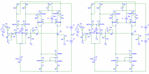
Attached is a test circuit with 2 configurations, the left has the cascode in input-ltp referenced to the emitters of the input-ltp, the right has this cascode referenced to gnd. The left circuit shows a THD of 0.00003%, the right one has 0.03%. The difference is factor 1000 ! How is that possible ?
Input was 2v 20khz, output 4v. Both have OLG of 3800 at 20khz. Without the cascode THD is 0.007%.
Mike
Attachments
Mike,
Probably it is a simulator artifact. I have had cases that output signal went down from several volts to just a few millivolts when referencing the supply of a circuit to some output (bootstrapping the supply). In very similar cases is worked OK. What sim do you use, Pspice?
In any case, the HD figures of a sim are notoriously inconsistent anyway. What are the differences with an FFT?
Jan Didden
I have been experimenting with cascodes, current sources and LTPs in real circuits with real transistors and I have been able to observe that kind of effects, altough not so strong.
All the trouble comes from some assumptions that we make when designing circuits but that are not true with real components. Three of these assumptions are: Constant Vbe, constant hFE and constant capacitances.
For example, I have been able to measure Vbe changes of a few milivolts associated with Vce changes of a few volts. High gain circuits are evil because they amplify also all these unwanted erratic signals due to Vbe, hFE and Cbc modulation. That's why keeping Vce constant, or at least, keeping the AC component of Vce small and strictly proportional to the audio signal, reduces distortion not only in simulation but also in real life (altough not to 0.0000003% ).
).
Both in my LTP and its associated current source I was able to measure Ic modulation due to the Vce sweep caused by the input signal and the power supply ripple voltage. Even after taming most of the error component coming from the PSU and isolating the error component coming from the input signal voltage sweep, the high content of 2nd harmonic was still quite evident at first sight (even with the oscilloscope in the 1mV/div range and picking up a lot of RF noise that blurred the waveform).
Anyway, the worst modulation by far is the one coming from power supply ripple (the one from real power supplies, not from PSpice voltage sources ). I have found really really difficult to reduce it, but this is the key to good PSRR and "clean" circuit behaviour.
All the trouble comes from some assumptions that we make when designing circuits but that are not true with real components. Three of these assumptions are: Constant Vbe, constant hFE and constant capacitances.
For example, I have been able to measure Vbe changes of a few milivolts associated with Vce changes of a few volts. High gain circuits are evil because they amplify also all these unwanted erratic signals due to Vbe, hFE and Cbc modulation. That's why keeping Vce constant, or at least, keeping the AC component of Vce small and strictly proportional to the audio signal, reduces distortion not only in simulation but also in real life (altough not to 0.0000003%
).Both in my LTP and its associated current source I was able to measure Ic modulation due to the Vce sweep caused by the input signal and the power supply ripple voltage. Even after taming most of the error component coming from the PSU and isolating the error component coming from the input signal voltage sweep, the high content of 2nd harmonic was still quite evident at first sight (even with the oscilloscope in the 1mV/div range and picking up a lot of RF noise that blurred the waveform).
Anyway, the worst modulation by far is the one coming from power supply ripple (the one from real power supplies, not from PSpice voltage sources
). I have found really really difficult to reduce it, but this is the key to good PSRR and "clean" circuit behaviour.MikeB said:Attached is a test circuit with 2 configurations, the left has the cascode in input-ltp referenced to the emitters of the input-ltp, the right has this cascode referenced to gnd. The left circuit shows a THD of 0.00003%, the right one has 0.03%. The difference is factor 1000 ! How is that possible ?
Input was 2v 20khz, output 4v. Both have OLG of 3800 at 20khz. Without the cascode THD is 0.007%.
The left input LTP is effectively bootstrapped , this decrease the Miller capacitance of the LTP input transistors , and remember that you are measuring distortion at 20 KHz.
Certainly at 1KHz , the difference in distortion will not be so dramatic.
Yes, that's right, this effect is frequency dependent and caused by Vce variations that are barely existing in the left version. Gladly pspice models the dynamic behaviour of bjts. It's frightening how easily a circuit can be mis designed causing "horribly high" distorted trebles.
BUT, it is still fascinating where the problem occurs, obviously the openloop distortion can't be increased by factor 1000 by that. (that would be 57%)
Mike
BUT, it is still fascinating where the problem occurs, obviously the openloop distortion can't be increased by factor 1000 by that. (that would be 57%
)Mike
Hi, Mike,
How are you
I really amazed by NP's patent 4,107,619. It is dated 1978, look at the drawing at the first page.
What amazed me more, is that it seems NP knows distortions that can be eliminated by feedback, and which ones cannot. So he cleverly advoids the distortion cause that cannot be eliminated by feedback. Distortions caused by non-linear internal transistor capacitance, for example, cannot be eliminated by feedback (I think....)
How are you
I really amazed by NP's patent 4,107,619. It is dated 1978, look at the drawing at the first page.
What amazed me more, is that it seems NP knows distortions that can be eliminated by feedback, and which ones cannot. So he cleverly advoids the distortion cause that cannot be eliminated by feedback. Distortions caused by non-linear internal transistor capacitance, for example, cannot be eliminated by feedback (I think....
)Yes, in fact this is a distortion that can not be compensated by feedback. Applying more feedback even worse things as it does not reduce anything, but the increased openloop gain will amplify these effects. I believe this is the trap where many made the experience that more feedback sounds worse (except the stability thing).
Why ?
The distortion is created outside the feedback loop...
The signal is already distorted at the input of the amp, there is no way to compensate THAT with feedback.
This is caused by dynamic miller capacitance, creating a reactive input distorting the signal BEFORE it enters the amp. The same thing happens at the feedback node, resulting in non functional feedback plus the distortions generated at input. The amp itself works correctly, but gets fed with defect signals. That should be one reason why jfets sounds different, they create different distortions.
The simplest way out is to increase supply voltage, reduce swing at input and use good bjts. Or use correct working cascodes, they can nearly kill this effect. (reduce it by factor 1000) These cascodes make the amp also tolerant to high impedance source.
This cascoding can be simply done with jfets around the input devices.
Mike
Attachments
Distortions that taint the error signal calculation (the difference between the actual output and the desired value) cannot be eliminated by feedback.
In other words: Input differential stage should be as linear as possible (and should feature high PSRR). Once the error signal is precisely calculated, high open loop gain will do the rest (provided that a reliable path for the amplified error signal to reach the output exists).
EDIT: I have just fallen in love with these JFET cascodes!
Yes, these jfet-cascodes are so simple, they immediately burnt into my mind when i first saw them !Yes inputstage should be linear, but even more important is to have a not reactive input. A linear inputstage can be easily done by using high openloop gain, giving a minimal swing in input-ltp.
Mike
MikeB said:
Why ?
The distortion is created outside the feedback loop...
The signal is already distorted at the input of the amp, there is no way to compensate THAT with feedback.
What about , if you rearrange the amp for inverting configuration...
MikeB said:Yes, i forgot this one, giving a minimal signal at the input ! But this gives problems with high impedance sources ?
Yep!...there are no free lunches .
[[ For higher freqs the propagation delay might increase this voltage, again increasing distortion for higher freqs ? ]]
Yes. As the frequency increase , the error signal (the real input of the amp) at the bases of the LTP increases... in function of the compensation of the amp.
MikeB said:- the left has the cascode in input-ltp referenced to the emitters of the input-ltp,
- the right has this cascode referenced to gnd.
The left circuit shows a THD of 0.00003%,
the right one has 0.03%.
The difference is factor 1000 ! How is that possible ?
Input was 2v 20khz, output 4v. Both have OLG of 3800 at 20khz. Without the cascode THD is 0.007%.
Mike
Matching and perfect input pair operation
is the key to performance in a global feedback amplifier.
We can say input pair in LTP (long tailed pair) is the very heart of circuit
Anything goes wrong here, it will not matter
whatever other stages or output transistors you have
Important factor to look at is Voltage C-E of input pair.
In left circuit, Vce is nearly constant, even if input is 1 Vrms.
In right circuit, Vce changes with 1 Vrms.
so, I find it naturally left circuit should perform better
but not that much!
simulation shows, that
- not only should the pair be good matched, Q1 = Q2
- but also good if both Q1,Q2 has got a CONSTANT environment.
it can be discussed, what input sensitivity an amp should have
and how much or little global gain
that is, how much input voltage
because this will effect Vce of input transistors
Say we have global V-gain of 200
For 20 Volt output, is only 0.1 volt RMS input.
Input sensitivity contra total voltage gain, resulting in 1 Vrms input
is a sort of compromise, that has proven good.
It is not good with too high input voltage,
but not very good with high closed loop gain .
Hi, Mike
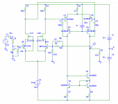
How about figD? It gives constant voltage plus constant current, minimalizing distortions due to internal cap non-linearities in diff pair? (but the gates of the fets should be to emitors like you draw). Peufeu is using this for "Memory Distortion".
How about figD? It gives constant voltage plus constant current, minimalizing distortions due to internal cap non-linearities in diff pair? (but the gates of the fets should be to emitors like you draw). Peufeu is using this for "Memory Distortion".
Attachments
Tube_Dude said:
What about , if you rearrange the amp for inverting configuration...
Then you need only to change input to sziklai, keep Mike's cascode configuration and you have halcro input.
MikeB said:Yes, in fact this is a distortion that can not be compensated by feedback. Applying more feedback even worse things as it does not reduce anything, but the increased openloop gain will amplify these effects. I believe this is the trap where many made the experience that more feedback sounds worse (except the stability thing).[snip]Mike
Mike,
Beg to disagree. This is simply a case where the open loop linearity is much improved by the bootstrapping. So, the HD is much smaller to begin with, and then again the fb decreases it. There is no hint whatsoever that nfb doesn't educe this distortion or any other distortion existing within the loop enclosed by the nfb.
Jan Didden
janneman said:
Mike,
Beg to disagree... There is no hint whatsoever that nfb doesn't educe this distortion or any other distortion existing within the loop enclosed by the nfb.
Jan Didden
Jan, that distortion (source impedance and nonlinear input capacitance due to nonlinear miller capacitance of the BJT = nonlinear filter) indeed is outside the NFB. You can only hope to balance it by providing the exact same impedance and capacitance on the othe LTP input. Or alternatively, include that part into the NFB by using an inverting configuration. Everyone who has used FETs or MOSFETs in input LTPs knows it well
because it is so much higher with these. I recall National Semi or Analog Devices having an interesting app note where they bootstrapped the negative supply rail of a FET input OPAMP to reduce it's distortion using the same principle. Many FET input amps tend to operate their FETs at close to maximum VDS or bootstrap cascoded exactly for this reason. Of course, nonlinear gain is another important factor but the distortion mechanism is different.Hi Jan !
Do you really believe that openloop linearity got increased by factor 1000 ? I had closely checked, openloop linearity and gain barely changed by the cascode, the problem is simply that the signal at the base of the + input is already distorted, the amp amplified what he got. The feedback signal was the same way distorted. As ilimzn pointed out, you could try to balance the impedances.
The effect was exaggerated in this circuit by low supply voltage and having the cascode close to the input swing.
Try this circuit in sims ! The errorvoltage says that there are no distortions (distortions canceled out at fb node). That's no hint whatsoever, naked measurings.
Mike
- Status
- This old topic is closed. If you want to reopen this topic, contact a moderator using the "Report Post" button.
- Home
- Amplifiers
- Solid State
- A small "riddle"...