Hi
I include 2 scope traces of my diy power amp output:
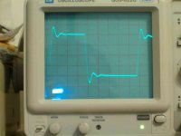
1) Load = 8ohms parallel to 2uF at 4vac with LR output filter. R=1 ohm, L = ?
(By the way , I left the RC in series between the output and ground for the 2 waveforms. R = 10, C = 68nf.)
I include 2 scope traces of my diy power amp output:
1) Load = 8ohms parallel to 2uF at 4vac with LR output filter. R=1 ohm, L = ?
(By the way , I left the RC in series between the output and ground for the 2 waveforms. R = 10, C = 68nf.)
Attachments
Hi Fab,
the Thiel network on the output is there to do a number of jobs.
The inductor separates load capacitance from the NFB loop to help keep the stability correct. i.e. phase margin above design limit.
The cap gives the amp a load at very high frequencies, again to aid stability. Can someone explain this mechanism to me?
The combination provides a filter to remove back emf and interference from entering the NFB loop and modulating the inverting input.
As Jcx said the ringing between the inductor and the load is normal and cannot be eliminated but can be damped, as your wave shows.
If you omit it you eliminate the ringing but open up the amp to the stability and back emf problems that must be solved by other design options.
jcx said:where are you looking? - what you really want to see not ring is the output Q/feedback connection - looking at the L-speaker term will show ringing when the L is doing its job
Hi jcx,
I am monitoring on the Power amp circuit board directly, not at speaker terminals. I want to characterize the amp. By the way, there is no real speaker connected but a dummy load of course.
AndrewT said:Hi Fab,
the Thiel network on the output is there to do a number of jobs.
The inductor separates load capacitance from the NFB loop to help keep the stability correct. i.e. phase margin above design limit.
The cap gives the amp a load at very high frequencies, again to aid stability. Can someone explain this mechanism to me?
The combination provides a filter to remove back emf and interference from entering the NFB loop and modulating the inverting input.
As Jcx said the ringing between the inductor and the load is normal and cannot be eliminated but can be damped, as your wave shows.
If you omit it you eliminate the ringing but open up the amp to the stability and back emf problems that must be solved by other design options.
Hi AndrewT,
I notice that with the LR filter, the waveform is damped. I also notice that without the LR filter, the damping is less obvious but the peak is a lot less . My questions is then: what is the best way to get the best more natural sound into the speaker and desensibilizing the amp circuit to load impedance. I use voltage overall negative feedback of about 40 db. I have noticed that most amps today (from what I have seen) do not include the LR circuit. Remember that I use a dummy load, does someone might consider a real speaker load to adjust amp parameters?
Thanks
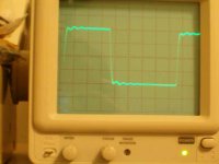
In the first picture you can see the "natural" response of the amplifier when driving a purely resistive load above the audio band because the load capacitor is isolated by the inductor (it suggests to use a lower impedance RC network, may be 4.7ohm and 220nF, or stronger frequency compensation in order to damp better that ringing).
In the second picture, the capacitor connected as a load is interacting with the amplifier at higher frequencies (there is no inductor to isolate it) and reducing phase margin but also gain, so the overall result is no overshoot. However, nasty things may happen in the Mhz range.
By the way, some modern amplifiers lack a RL network in series with the output to reduce costs and save space (and you may see people complaining about them oscillating when things like exotic speaker cables are employed). Anyway, adding that RL network is a good design practice because it prevents external stuff to interact with the amplifier above audio frequencies and leaves it only loaded with its internal RC network thus yielding consistent RF behaviour regardless of the load.
Hi,
try sinewave into your 8R//cap. Use a range of voltage from 25% to 90% of max. and 105% of max.
use a range of caps 100nF to 2uF. these combinations will take some time.
Look for instability on the sinewave. @zero crossing, @halfway up/down the wave, @the top of wave form.
You might need to do this for a range of frequency, no guidance. Be careful you don't apply high voltage and high frequency to the output RC (Zobel).
Then repeat for with and without the inductor.
Hear from you in two or three days with your results.
Use your ears!
Hi fab,
The only way to be sure about such choices as you have to make here is to actually listen to the results.
The late JLH (UK audio Guru) told me in private correspondence that provided there were not more than 3 'wiggles' on the square wave, he considered this to be "sonically benign", but this is one listening trial I have not carried out for myself (yet!) and so I cannot verify this. I strive for 'clean' square waves, using my chosen speakers and cables.
I have never had reason to doubt anything JLH has said, and he made no mention of the amplitude of any overshoot, so I presumed that 'time' is more significant here than 'quantity', where any sonic effects are concerned.
Assuming this is so, then the first 'scope pic (with the output network) should sound better, but in any such listening trials and/or measurements like these, it should certainly give the best results if the intended speakers *and* cables are used. They will always present different complex impedances etc. to the amp's output, and are likely to have some effect on the choices you end up with for the best results.
Andrew,
The "mechanism" you query is all due to the defined 'loading' of the amp's output at HF by the series cap and R. With the (most?) frequently used 100n & 10R here as the Zobel network, this will roll-off the output (by grounding it) with a -3dB point at about 160kHz, off the top of my head. This therefore overcomes any potential problems due to 'unusual' speaker/cable effects at HF, where the amp could be looking into a very high impedance, otherwise.
To quote from Ben Duncan:
" Delivering HF is a problem to amps with high NFB, especially when it is global. The amount of feedback (loop-gain) is reducing in most amps well before 20kHz, and often, in high NFB amps, from 10kHz. The output impedance begins to rise at typically +6dB per Octave at frequencies above this point. Thus the reducing NFB makes the amp's output look inductive, and also develops an output impedance that increasingly interacts with any load capacitance..... to cause a lagging phase shift. If the extra phase shift is very much, and occurs at a low enough frequency, RF oscillation will result."
JLH explained this, similarly, to me before I had read Ben D.'s book "High Performance Audio Power Amplifiers".
Ben D. also points out it is imperative that any 'output network' should be placed outside of the feedback network if it is to be of any benefit, and that amps without output inductors (except non, or very low feedback designs) are renowned for becoming unstable and even blowing up, when low inductance speaker cables are used.
One of JLH's mosfet designs (ETI 1984) initially had no output inductor//resistor arrangement and he specifically pointed out that with this design, these components were unnecessary, although all of his designs used the Zobel series cap and R to ground. When this same design was published subsequently (ETI 1989) with some minor modifications, the inductor had re-appeared, and being surpirised by this, I queried it's later inclusion.
JLH's response to this was that, in the intervening years, he had received a few grumbles from some constructors who had used 'unusual' speaker cables with the earlier amp, and they had experienced some oscillation problems, so this was the easiest way of avoiding this possibility.
I hope this helps.")
Hi fab,
The only way to be sure about such choices as you have to make here is to actually listen to the results.
The late JLH (UK audio Guru) told me in private correspondence that provided there were not more than 3 'wiggles' on the square wave, he considered this to be "sonically benign", but this is one listening trial I have not carried out for myself (yet!) and so I cannot verify this. I strive for 'clean' square waves, using my chosen speakers and cables.
I have never had reason to doubt anything JLH has said, and he made no mention of the amplitude of any overshoot, so I presumed that 'time' is more significant here than 'quantity', where any sonic effects are concerned.
Assuming this is so, then the first 'scope pic (with the output network) should sound better, but in any such listening trials and/or measurements like these, it should certainly give the best results if the intended speakers *and* cables are used. They will always present different complex impedances etc. to the amp's output, and are likely to have some effect on the choices you end up with for the best results.
Andrew,
The "mechanism" you query is all due to the defined 'loading' of the amp's output at HF by the series cap and R. With the (most?) frequently used 100n & 10R here as the Zobel network, this will roll-off the output (by grounding it) with a -3dB point at about 160kHz, off the top of my head. This therefore overcomes any potential problems due to 'unusual' speaker/cable effects at HF, where the amp could be looking into a very high impedance, otherwise.
To quote from Ben Duncan:
" Delivering HF is a problem to amps with high NFB, especially when it is global. The amount of feedback (loop-gain) is reducing in most amps well before 20kHz, and often, in high NFB amps, from 10kHz. The output impedance begins to rise at typically +6dB per Octave at frequencies above this point. Thus the reducing NFB makes the amp's output look inductive, and also develops an output impedance that increasingly interacts with any load capacitance..... to cause a lagging phase shift. If the extra phase shift is very much, and occurs at a low enough frequency, RF oscillation will result."
JLH explained this, similarly, to me before I had read Ben D.'s book "High Performance Audio Power Amplifiers".
Ben D. also points out it is imperative that any 'output network' should be placed outside of the feedback network if it is to be of any benefit, and that amps without output inductors (except non, or very low feedback designs) are renowned for becoming unstable and even blowing up, when low inductance speaker cables are used.
One of JLH's mosfet designs (ETI 1984) initially had no output inductor//resistor arrangement and he specifically pointed out that with this design, these components were unnecessary, although all of his designs used the Zobel series cap and R to ground. When this same design was published subsequently (ETI 1989) with some minor modifications, the inductor had re-appeared, and being surpirised by this, I queried it's later inclusion.
JLH's response to this was that, in the intervening years, he had received a few grumbles from some constructors who had used 'unusual' speaker cables with the earlier amp, and they had experienced some oscillation problems, so this was the easiest way of avoiding this possibility.
I hope this helps.
A few night thoughts from me.
Firstly it would help, fab, if you can give the horizontal time scale (I did not notice you giving the square wave frequency). Meaning that those oscillations may be totally above the audio band and irrelevant. And yes, it will help to load with a speaker equivalent load; although the impedance usually rises with frequency and has less effect than a fixed load resistor.
The Zobel network is a way of "bringing in" a load to the amplifier (as Bobken explained) above the audio band, so that it does not see a high impedance because of loudspeaker impedance rise as stated above, but also does not see this load in the band so as to waste power in it. The probelm often overlooked is that it is fine once the C-reactance is small compared to the 10 odd ohm of the resistor, but somewhere on the way there this load will present a 45 degree phase angle [where Z(C) = R] which some circuits do not like. It is not a universal cure-all.
I presume the L-R network mentioned is an L with damping R in parallel, all in serie with the load. This should be effective only above the audio band and thus not influence the sound at all. In my own design (8 ohm load) I use 20 uH with 22 ohm in parallel; this L becoming 8 ohm only at 60 KHz. My amp does not like the Zobel; I connect a 680 ohm 5W resistor permanently over the loudspeaker terminals, wasting about 1,2% of energy all the way. With the L it can tolerate any sort of load, even short-circuit (obviously not with any degree of input signal because the feedback is then off). Without the L the output transistors blow in 1 mS flat because of h.f. instability with output shorted, and will not tolerate an output capacity of over 15 nF - this just to illustrate the effectiveness of that L.
As Ben Duncan stated, such an "undesirable" state can be piously cured by an early enough roll-off (e.g. by Cdom). But if this cuts well inside the audio band you have a high-order harmonic generator, which WILL give an audible effect. There are few circuits with negligible phase shift up to 20 KHz; the price of that is careful stability design and a lower margin than over-compensated circuits. But this is slightly off-thread.
Regards.
AndrewT said:
The cap gives the amp a load at very high frequencies, again to aid stability. Can someone explain this mechanism to me?
Negative feedback + open loop gain makes the output resistance/impendance of an amp small. This resistance and the load capacitor interact to provide another pole. If the frequency is low, that pole is far away and does not mess with your amp. As frequency increases, the open loop gain drops. The outpuut resistance of the amp rises (beacause of NFB and reduced open loop gain) and moves that pole that did not cause troubles at LowFreq. It is not imperative that it will cause trouble with a given capacitance, but that is the mechanism and is what always happens. Note that for every amplifier there is an arbitrary value that makes the amplifier unstable beyound that margin. Sometimes a similar effect is used to stabilise the amp. The series RC connection (on the output) is used to affect the amplifier's gain and phase and make it stable. If done wrong wil make your amp burn, sorry.

Hi all,
For the scope traces I used 10K Hz square wave.
" presume the L-R network mentioned is an L with damping R in parallel, all in serie with the load. "
yes that is correct.
In trying to summarize some comments:
1) should the RC zobel network be adjusted to a specific amp response for even better damping? And the LR too?
2) I still see hi-fi amps schematics without RL filter. Is the R-8 ohms in parallel with 2uF non-realistic so the RL filter is not really necessary in real life, or "exotic" (what charactistics does it have?) cables do not exist anymore?
3)I have already tried different caps load from 1nF to 2UF but I though it was more the phase and gain margin of the amp circuit that had more influence. Do you suggest that the zobel RC filter and the RL filter have an impcat too. For this test, only at about 3.3 nF it gave some oscillation with 10K H z square wave. All other caps values worked with no problem (1nF, 2.2nF, 4.7nF, 10nF, 22nF, 47nF, 100nF, 220nF, 470nF, 1uF, 2uF). Does it mean that all possible values should be tested?
4) Trials and errors listening tests: this is what I want to avoid when searchng info on this forum.
It seems to me that the RC zobel and RL filters are something important for the amp performance so I thought that there were more "basic" accepted rules.
fab said:Hi all,
For the scope traces I used 10K Hz square wave.
For this test, only at about 3.3 nF it gave some oscillation with 10K H z square wave. All other caps values worked with no problem (1nF, 2.2nF, 4.7nF, 10nF, 22nF, 47nF, 100nF, 220nF, 470nF, 1uF, 2uF). Does it mean that all possible values should be tested?
It seems to me that the RC zobel and RL filters are something important for the amp performance so I thought that there were more "basic" accepted rules.
Maybe it is the capacitor itself? Try another unit, preferably some wima's or other well designed capacitor. You can experiment with different technologies. Ceramic, plastic, mica, electrolyte...
Did you do a frequency sweep with other capacitor values? Try it, maybe you can find something that gives a clue about what is going on.
Zobel, L, always welcome. Good design practice.
Just a few further brief thoughts (bed-time here!)
Firstly we can forget about cable capacitance having much of an effect in audio; it is mostly too low unless you are using tens of metres or have some pretty weird cable. But on another thread SY (whose comments can be respected) mentioned that some amplifiers are not happy even with normal cable, as in that they tend to go unstable, I presume above the audio band. I accept he has seen such results, although I would not like to know about such critical designs........
The slight oscillations in the first oscillogram appear to be of the order of 120 KHz and regarding direct effect in audio can be ignored. That graph with the RL to me indicates that the amp saw an increased load at 120 Khz - the reactance of the L - compared to only a load resistance without it. Analysis will indicate exactly what is going on.
The cap in serie with the Zobel R is as said simply to keep it from shunting the load inside the audio band. As such the value is not important but might depend on the amplifier's "demands" at supersonic frequencies. When there is time I will put this on a Spice program and see what comes up, and come back here (a little tied up at present).
Regards.
Hi Iggz,
I understand most of your reply, but can you explain this moving pole?
As frequency increases, the open loop gain drops. The output resistance of the amp rises (because of NFB and reduced open loop gain) and moves that pole
I understand most of your reply, but can you explain this moving pole?
Hi Fab,
go back to that 8r//3n3F dummy load. Check for that amplifier oscillation. Probably in the 300kHz to 10MHz range. Not the natural resonance that the L & dummyR produce @ 100kHz to 150kHz.
Try to remove it with adjustments to your compensation.
Finally, the testing with dummy loads and // caps is an attempt to simulate the use of different speaker and cable combinations and over a range of frequencies. A speaker changes it's reactance from resistive (at DC) to capacitive then through resistive to inductive and so on as the frequency goes all the way up.
go back to that 8r//3n3F dummy load. Check for that amplifier oscillation. Probably in the 300kHz to 10MHz range. Not the natural resonance that the L & dummyR produce @ 100kHz to 150kHz.
Try some other similar value caps and sweep the frequency to see if they cause oscillation as well.do a frequency sweep with other capacitor values?
Try to remove it with adjustments to your compensation.
Finally, the testing with dummy loads and // caps is an attempt to simulate the use of different speaker and cable combinations and over a range of frequencies. A speaker changes it's reactance from resistive (at DC) to capacitive then through resistive to inductive and so on as the frequency goes all the way up.
Make your mind up time.
Hi fab,
This appears to be a situation where you wish to 'have your cake and eat it' and this rarely works out in real life.
You started off by saying "what is the best way to get the best most natural *sound* " etc., but now you say you wish to "avoid trials & errors listening tests" for this!
Regrettably, all amps vary with regard to their stability issues and how speaker cables and speakers themselves will affect this area. Therefore, there simply is no 'one size fits all' answer here.
Many posters have tried to explain the reasons for these output network components (including myself) but unless you have incipient instability, which shouldn't be the case anyway, I doubt that you will ever *hear* any real differences here. This, of course, assumes that the components don't actually roll-off the signal anywhere near to the audio range, which they shouldn't.
Otherwise, having carried out numerous *listening tests* on similar areas, myself, in my experience you will *hear* far greater effects from the type of components used than with any minor variations in the square-wave overshoot at say 10kHz, or above.
For good reason (Luminaries like) D.Self, B. Duncan, and JLH all state that the output inductor should be air cored (and subjectively I found this to be true) and two of the above who also comment on the sonic effects, agree that these effects (which are always to give a ripple on the square wave) are of no consequence, sonically.
JLH." ... a ripple on the square wave/reactive load test waveform, which is an inevitable effect of any steep cut, low pass filter", and "provided there are not more than 3 wiggles on the square wave, this is sonically benign"..
B.D. "... which may have to be accepted as one of those compromises that measures bad but sounds fine".
In my own experiments, I achieved better results with regard to overall stability and 'clean' square waves (initially without any output inductor//damping resistor) through varying the compensation caps. Then, where a *suitable* damped output inductor has been added later, I could hear no difference to the sound, at all.
However, experiments with different components (of the same nominal values) being used for the cap and resistor of the output Zobel, showed marked changes to the overall sound. To show how seriously I take this, I have ended up using $30 worth of components here for this Zobel alone, in a stereo amp.
Such expenditure nearly breaks my heart, but every alternative component I tried out had some different (and more adverse) effect on the outcome, and my present best choice here is to use MIT RTX (multiple-section) polystyrene & tin-foil caps, together with a Caddock resistor.
Varying the values of these (within reason) has little (if any) sonic effect, but changing to an alternative type/make of component alters the sound by an unintuitive degree, but which I cannot ignore.
Running for a short while without any Zobels, sounded even better still, but I am not prepared to take a chance on this on a long-term basis.
No amount of theorising, simulation, nor measurements (which I have also done!) explain the full 'sonic' picture here, and that is why the very best designs have had hours of development-time spent on them, painstakingly listening to these kind of effects, and consequently also explains (not necessarily justifies!) to some extent, their often apparently inordinately high costs.
You can see from posts on this Forum just how much trouble designers like Jonathan Carr, John Curl, Hugh Dean, Peter Daniel, and many others will go to to achieve the best possible *sound* from their designs, on top of the already technically well thought-out circuits they use.
So, as I said in post #8, if you really do wish to end up with the best *sonic* results, you have no choice but to carry out these trials for yourself, however inconvenient/unattractive this may be, and no-one else can tell you exactly what is best to make it easy for you. If, however, you wish to maximise the results from purely a measurement point of view, that is a different matter altogether.
Regards,
AndrewT said:Hi Iggz,
I understand most of your reply, but can you explain this moving pole?
This holds true for voltage feedback voltage amplifiers, wich is 99% of all amplifiers made.
I don't know any equation by hart, but roughly the uotput impendance of the amplifier is:
Zout=Z0/(1+beta*A)
Z0 is the output impedance withouth feedback
beta is the feedback factor
A is the open loop gain, which is frequency dependant
assume a beta of say 0.01
a A of 100000 at DC
and a Z0 of 10 Ohm, purely resistive
Zout=0.00999 Ohm at DC.
Let say that the A at 10kHz is 1000, a change of 40 dB, others parameters unchanged:
Zout=0.909 Ohm
Asume that we have a 1uF capacitor at the output. Zout and the capacitor compose a impedance divider, this is where we take our feedback. Pole at DC is:
POLE_dc=1/(2*pi*Zout*C)= 15.9 MHz
The same pole at A=1000 (f=10kHz), Zout is now 0.909 Ohm:
POLE_10kHz=same equation, different Zout= 175 kHz
When the amplifier is excited with 10kHz the pole moves/is located at 175kHz. The same pole is located at 15.9MHz. Both of the values are located away of the 20kHz region in this case. However this is not necesarily so at other frequencyes and other Zout/C combinations. How this affecta the amplifier, is it good or bad, is in the domain of the stability analysis. In other words, it is higly dependant on the amplifier itself (and the components the amplifier is composed of + the topology of the circuit and even layout).
In my experience, an amplifier may be oscillating like hell, distorting badly, cross-conducting like if it were class-A and starting to smoke, while most people will still tell you that it sounds right. In other words, listening is definitely not the way to optimize the behaviour of an amplifier above the audio band. Analyzing such behaviour with any other tool than an oscilloscope is to me an absolute waste of time.
Concerning air cored output inductors, they will obviously produce a stray magnetic field proportional to the loudspeaker current and to its frequency, that will obviously cause some degree of feedback over the small signal circuits and signal wires. So these inductors should be placed away from the amplifier circuit itself, in the output binding posts for example. A feet or so (30cm) is already a good distance.
Concerning air cored output inductors, they will obviously produce a stray magnetic field proportional to the loudspeaker current and to its frequency, that will obviously cause some degree of feedback over the small signal circuits and signal wires. So these inductors should be placed away from the amplifier circuit itself, in the output binding posts for example. A feet or so (30cm) is already a good distance.
Hi Eva,
Regrettably, in your anxiety to disagree (a trait I have seen before in some other posts) you have not read (or perhaps understood) what I said here.
The original query (this was clarified subsequently by fab, and as I specifically reiterated in my previous post) was about the *sonic* differences (or preferences i.e. "best most natural sound") of the two different square-wave forms which had been shown.
To take your comments:
"oscillating like hell, cross conducting, starting to smoke" etc.
Where on earth does this come into the discussion?
I certainly have gone to a lot of trouble to point out that obtaining stabilty is important in the first place, and, together with several other posters, have suggested some ways and means of achieving this. Also, because it is fundamental to the 'stability' issue, in this last post I even suggested it was best to look at the compensation caps first, as no-one (IIRC) had yet mentioned this.
"Listening is definitely not the way to optimise the behaviour of an amplifier above the audio band".
Of course it is not, and no-one has suggested that it was!
What I have said (supported by several references) is that any such sonic differences are unlikely to be heard when conducting *listening tests*. Therefore, they are a red-herring as far as the sound goes in this instance, and no choice is likely to be possible here, based on these wave-forms.
I have looked many times, and for many weeks at such 'scope waveforms, and as I have also said before, there is aurally no difference (IME) when I have carried out these tests.
I simply went on to point out in what I hoped was a helpful comment to someone who had asked about the *sonic* preference here, what *does* most certainly make a noticeable difference to the sound in my experience.
If and when you achieve the experience of some of the people I mentioned before, you will also appreciate that careful choice of components in any audio circuit is also important, and can make a good amp into an excellent one, even if if this not intuitive to you now.
Measurements alone are simply not sufficient to tell the entire story here, whether you accept this or not.
I don't wish to start any retalliatory action here, but your comments on output inductors and crosstalk etc. , do need some clarification if one is to believe Doug. Self (who is far from being a 'subjectivist'!) and my own ears.
In his book "Audio Power Amplifier Design Handbook" he devotes 6 pages to this subject, so it is not nearly as simple and straightforward as you imply. Perhaps this is as well, since many (most?) amps will probably not have an enclosure sufficiently large to allow for your suggested 30cm.
Doug Self has carried out many trials here, and with output inductors which are orientated in the same way (the worst case scenario, similar almost to a transformer, and which he considers to be "the least favourable combination") he measured -126dB total crosstalk at 1kHz, with merely 110mm spacing between them. He sensibly comments with some confidence that "this is not going to be a problem".
I realise that you also include other parts of the circuitry in your comments (at low-level) but cannot accept that they would be any more liable to 'pickup' here than a similar coil tested in a 1:1 'semi-transformer' configuration.
How did you arrive at your recommended and possibly almost unattainable 30cm, which you say is already a good distance?
Regards,
I arrived at that number by measuring (or no longer being able to measure) the maximum voltage induced in a 10cm diameter loop of wire at 10Khz (that as you have mentioned, is orientation dependent). You can't realiably measure the crosstalk in the own amplifier because the feedback effects are taking place inside it and there may be positive or negative feedback, or a mixture of them over various stages. I was also able to measure induction with improper wiring, but that's another story.
- Status
- This old topic is closed. If you want to reopen this topic, contact a moderator using the "Report Post" button.
- Home
- Amplifiers
- Solid State
- Power Amp output inductance or not?