what actually sets the current is the 10k trimpot
so any power supply ripple or changes
will upset current source
( = low Power Supply Rejection , PSRR )
I know, that's why in the definitive design I want to replace the 20K resistor by a jfet current source feeding the trim (surely an other value than 10K)
So you think that the design with the 2 bipolars is ok???
Thanks
It will work,
but there has to be a better way to do it.
Now what JFET can run 100 mA ??
The only one I know, is that Power JFET at Pass Labs
they all are making a big fuzz about.
Lets see what new sensation NP have in store for next year,
to make another big fuzz about ....
")
but there has to be a better way to do it.
Now what JFET can run 100 mA ??
The only one I know, is that Power JFET at Pass Labs
they all are making a big fuzz about.
Lets see what new sensation NP have in store for next year,
to make another big fuzz about ....
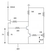
I wonder how you could get 7V in the left side if you adjust for 8.2V in the right side. Note that the two BE junctions add voltage to the reference rather than substracting.
Also, I think that it could be simplified by replacing the 70 ohm resistor by a potentiometer and connecting the base of the NPN transistor to its wiper and its emitter directly to -30V. This will also improve PSRR a lot, since in your circuit the reference adjustment is directly modulated by power supply ripple, while in the circuit that I propose the modulation happens indirectly through Vcc modulating Ic through the 10k resistor, Ic modulating Vbe.
The best simple current source that I have found is the two-transistor one that forces a Vbe drop in the sense resistor though feedback. It improves a lot with the addition of a zener and a resistor to keep the Ic of the sense transistor more constant and avoid Vbe modulation effects with Ic. The current source transistor is inherently protected from these effects.
The two-diodes-and-a-transistor current source has somewhat worse performance, particularly when the current through the diodes is modulated by supply ripple. It also suffers from Vbe modulation with Vce changes in the current source transistor.
hugobors said:No I don't want to replace the mosfet by a jfet, I want to replace the 20K resistor by a jfet in cs configuration... so my adjustable tension reference will be power supply noise independant.
MOSFET you have.
okay, sorry I took it for a JFET
I wonder how you could get 7V in the left side if you adjust for 8.2V in the right side. Note that the two BE junctions add voltage to the reference rather than substracting.
Sorry for the mistake......
Also, I think that it could be simplified by replacing the 70 ohm resistor by a potentiometer and connecting the base of the NPN transistor to its wiper and its emitter directly to -30V.
Yes I know but I need to drive several mos and so couln'd make all adjustable with all bibolar around each one.
t improves a lot with the addition of a zener and a resistor to keep the Ic of the sense transistor more constant and avoid Vbe modulation effects with Ic
Can you explain more or post a shematic???
And so what's the best solution for me???
Try this:
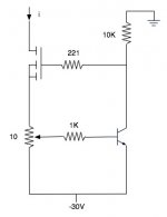
I have chosen component values for a 100mA typical current adjustment and 30V supply as you show in your schematic.
The bipolar transistor controls the gate voltage to force the voltage drop across the 220 ohm resistor to be equal to the multiple of Vbe adjusted with the potentiometer.
That working principle is precise, but has a main flaw: The Vbe of the control transistor is not constant, it changes according to its collector current. This means that biasing the control transistor directly from a resistor to ground produces poor PSRR because ripple on the PSU rails will affect the preset current value. To reduce that undesirable effect by an order of magnitude, the collector current through the control transistor is kept more or less independent of PSU voltage by employing a zener and an additional resistor.
This is still far from perfect, because the instantaneous Vgs setting for the MOSFET to conduct 100mA depends on its instantaneous Vds, and the Ic of the control transistor is in turn dependent of Vgs, but keeping Vds above 10V minimizes that effect. Trying to compensate for it would require to bias the control transistor with an additional current source (complexity!!).
I have experienced oscillation sometimes in that kind of circuits, so the 47pF capacitor is recommended. Always check with oscilloscope.
An externally hosted image should be here but it was not working when we last tested it.
I have chosen component values for a 100mA typical current adjustment and 30V supply as you show in your schematic.
The bipolar transistor controls the gate voltage to force the voltage drop across the 220 ohm resistor to be equal to the multiple of Vbe adjusted with the potentiometer.
That working principle is precise, but has a main flaw: The Vbe of the control transistor is not constant, it changes according to its collector current. This means that biasing the control transistor directly from a resistor to ground produces poor PSRR because ripple on the PSU rails will affect the preset current value. To reduce that undesirable effect by an order of magnitude, the collector current through the control transistor is kept more or less independent of PSU voltage by employing a zener and an additional resistor.
This is still far from perfect, because the instantaneous Vgs setting for the MOSFET to conduct 100mA depends on its instantaneous Vds, and the Ic of the control transistor is in turn dependent of Vgs, but keeping Vds above 10V minimizes that effect. Trying to compensate for it would require to bias the control transistor with an additional current source (complexity!!).
I have experienced oscillation sometimes in that kind of circuits, so the 47pF capacitor is recommended. Always check with oscilloscope.
This is more or less the same that I proposed, but you may have a hard time finding small non-wirewound 10ohm potentiometers, while values above 100 ohm are standard (that's why I used a separate potentiometer). Also, your circuit is not protected against misadjustment, so if you turn the wiper too close to the emitter the circuit may self-destruct (depending on the load). Additionally, in your circuit the current through the control transistor is modulated by power supply ripple, and this in turn will modulate its Vbe and will cause the output current to contain some PSU ripple. My circuit circumvents that with an additional resistor and a zener. Your circuit will be fine if you don't need extreme precision, though.
Chose the resistor values so that the zener is biased with approx. 5mA (some current is required to get a low impedance from the zener, but the actual current will depend on supply voltage, so you can put the midpoint here) and the control transistor with 2mA or so (may be 5mA if you want more bandwidth).
Remember to check for oscillation, and if it happens, fix it with a small capacitor like my schematic shows. Otherwise the current source will show very bad precision (I know because I have experienced it).
Remember to check for oscillation, and if it happens, fix it with a small capacitor like my schematic shows. Otherwise the current source will show very bad precision (I know because I have experienced it).
Problem.....
Hello,
Eva, I've tried your shematic but didnt' understand the 220R on the mosfet source, for the trim upside, this will give 3 mA in mos, and for downside around 15mA, but I need around 110mA... That's why I 've tried 10R, and this don't work.....WHY??????????????
Thanks
Hello,
Eva, I've tried your shematic but didnt' understand the 220R on the mosfet source, for the trim upside, this will give 3 mA in mos, and for downside around 15mA, but I need around 110mA... That's why I 've tried 10R, and this don't work.....WHY??????????????
Thanks
- Status
- This old topic is closed. If you want to reopen this topic, contact a moderator using the "Report Post" button.
- Home
- Amplifiers
- Solid State
- Current-Source idea