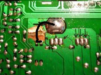
I have a Kenwood KAC-7201. I opened it up so i could solder some wires to the inside of the amp. i noticed that one trace was bubbled up for some reason so i blew on it to get some of the crap off of it and it blew away the trace foil. I am wondering how would be the best way of conencting that foil? or should i have an electrician do it? I have some pics of what i am talking about. the first pic is the close up, u can see on the right side of the trace that is broken, it is barely seperated. i even checked with a VOM and theres no connection.
I dont want to connect the amp and see if it works because from what i can see, this is an important part of it. it connects one of the big capacitors that are on the top of the circuit board so if my common sense serves me right, i should have this fixed(or fix it myself) b4 hookin it up")
I dont want to connect the amp and see if it works because from what i can see, this is an important part of it. it connects one of the big capacitors that are on the top of the circuit board so if my common sense serves me right, i should have this fixed(or fix it myself) b4 hookin it up
An externally hosted image should be here but it was not working when we last tested it.
An externally hosted image should be here but it was not working when we last tested it.
alright thanks. ill try the braid tomorrow. i dont know why but when i bought new ends for my soldering iron, i saw the braid and i had a really strong feelingi would need it for something but had no idea why so i dismissed that thought but now, i know why i had that feeling
i like the amp(for what i listen to) so what i did, i jsut made a fiberglass mount for it for my trunk and then this happens:-(. the mount is specifically to fit this amp perfectly so i was seeing what my options were before i tried to repair it.
i like the amp(for what i listen to) so what i did, i jsut made a fiberglass mount for it for my trunk and then this happens:-(. the mount is specifically to fit this amp perfectly so i was seeing what my options were before i tried to repair it.
Nigel Goodwin said:As suggested, for that to happen there has been a short somewhere, either the amp is faulty or there's been an external short (or quite possibly both!). It would be EXTREMELY rare for a PCB track that thick to fail under normal usage!.
You can see that they were trying to maximize the surface area -- and didn't do a good job, so instead of a trace they made a fuse -- a 100 mil trace of 1 oz copper should handle 4 amps or so -- if you have the problem, other people have the problem -- copper braid is a good idea -- but you can just take a short length of coaxial cable, remove the central conductor and use the braid to make a bridge--
i am wondering what other design flaws lie under the surface. make sure that there aren't idle pieces of copper on the top surface of the board.
there hasnt been any shorts. the reason y it looks like a nasty break is that there is a raised part of the surface under the break, the piece of copper was raised up and just flaked off. i took it to an electrician and he put a solid bridge of solder across it that small gap(didnt charge me either). do you guys agree that doin that will fix the problem? or so i need to just do solderbraid on it?
An externally hosted image should be here but it was not working when we last tested it.
I would see if the unit will work at low power with this repair at the current stage before proceeding with more work.
If it were my own amplifier, I would call it good if it is functional like this... that braid bridge is probably at least as capable of carrying current as the original trace.
If it were my own amplifier, I would call it good if it is functional like this... that braid bridge is probably at least as capable of carrying current as the original trace.
Hi,
The cause looks like someone else 'fiddled' with it.
Maybe overheated the board when soldering.
As for repair, I recommend a jumper-wire to replace the board trace.
A glob of solder easily breaks. It's a future failure point.
Solder a wire from one component to another.
The cause looks like someone else 'fiddled' with it.
Maybe overheated the board when soldering.
As for repair, I recommend a jumper-wire to replace the board trace.
A glob of solder easily breaks. It's a future failure point.
Solder a wire from one component to another.
Attachments
thanks for the advice. i am wondering tho, wouldnt doing that create resistance since those 2 small points are conected to the large trace? well, its in the path of it in parallel. i realize that if i connect the 2 small points to the large point of the capacitor(thats what the big solder point is) it will still be in parallel, just all of the current would have to go through those 2 small points to the cap instead of through the large flat trace. but i also realize that the trace is large but very thin.
thanks for the replies allready tho, they have helped alot
oh also, if it is a go ahead for soldering jumper wires, i ask 2 things: 1.) what gauage of wire should i use? im guessing maybe 18? 2.) if i do the jumper wires, should i desolder the solder bridges that were added?
thanks for the replies allready tho, they have helped alot
oh also, if it is a go ahead for soldering jumper wires, i ask 2 things: 1.) what gauage of wire should i use? im guessing maybe 18? 2.) if i do the jumper wires, should i desolder the solder bridges that were added?
silentblackhat said:oh also, if it is a go ahead for soldering jumper wires, i ask 2 things: 1.) what gauage of wire should i use? im guessing maybe 18? 2.) if i do the jumper wires, should i desolder the solder bridges that were added?
18 ga should be adequate.
I'd desolder the bridge if it were me.
Here is an update, kind of. i tried desoldering the beads with my soldering orin but it wont melt when i set my 15 watt iron onto of the braid(the braid is between the iron and the solder) but it melts relatively fine when i just touch the iron to the solder, should I use my 30watt iron on it? i was using the 15watt because its one thats grounded.
silentblackhat said:Here is an update, kind of. i tried desoldering the beads with my soldering orin but it wont melt when i set my 15 watt iron onto of the braid(the braid is between the iron and the solder) but it melts relatively fine when i just touch the iron to the solder, should I use my 30watt iron on it? i was using the 15watt because its one thats grounded.
Melt a small amount of solder onto the braid. This will melt when desoldering and kickstart the wicking action.
- Status
- This old topic is closed. If you want to reopen this topic, contact a moderator using the "Report Post" button.
- Home
- Amplifiers
- Solid State
- Car Amp trace broken, fixable?