Remember I said before I put a capacitor from the output to ground. I meant the speaker output which you probably all guessed. I didn't notice for a bit that I still had oscillations until I put a test signal into it and I seen a waveform that looked like AM. So I looked closer and found I had only reduced the amplitude by a lot as well as the frequency. I decided to play capacitor roulette for the last quarter of the day and found that if I put the 0.1uF from the op-amp output to ground then the oscillations quit completely. It was time to go home when I figured this out so I will go to work tomorrow and run some tests on it with Pantera, Metallica and some speakers.
Unless you are using an exotic op-amp that loves driving highly capacitive loads, I think that amp is going to sound really slow!
Suggest you try removing the 0.1uF from where it is now, and instead put it at the output as before, but with a 4.7 or 10ohm resistor first in series, as Chris (anatech) has suggested.
Then, add a small amount of capacitance across (in parallel with) the the 23K resistor (R14). 47pF or 22pF would be what I'd try first...
You could also put a capacitor to ground at the input (i.e. parallel with R62), just in case the AM signals are sneaking in at the input.
Cheers!
Good point. I ran it in simulatioion and the op-amp had to put out 10 ma or so at 1 kHz and then started increasing rapidly after that. One of the main problems is I don't have to many parts, like any resistors below 100 ohms. I have a 18 pF capacitor, so I will try that in the feedback path and also see if I can't get a better connection with the capacitor from speaker output to ground.
Hi Clem,
I was about to suggest the same treatment. Took the words right out of my mouth!")
David, in general, amplifiers and op amps do not like to see a pure capacitance to ground (or many other places). It's always good practice to scale the resistor in series with the cap to the impedance of the circuit location. There are exeptions to this.
-Chris
I was about to suggest the same treatment. Took the words right out of my mouth!
David, in general, amplifiers and op amps do not like to see a pure capacitance to ground (or many other places). It's always good practice to scale the resistor in series with the cap to the impedance of the circuit location. There are exeptions to this.
-Chris
I would put a resistor (100ohm to 1K) between the output of the op-amp and the input of the darlington, and a small capacitor (10 to 100pF) from the output of the op-amp to the non-inverting input. This will create a split-feedback system and will prevent the op-amp from trying to drive the darlington at RF and oscillate.
Standard op-amps may be expected to drive a small-signal emitter-follower without additional compensation, but a power darlington usually going to produce excessive phase shift when approaching its Ft.
Standard op-amps may be expected to drive a small-signal emitter-follower without additional compensation, but a power darlington usually going to produce excessive phase shift when approaching its Ft.
If I remember correctly, the two requirements for oscillation is a phase shift greater than 180 degrees and a gain greater than 1, is this correct? So as the frequency gets higher, the phase shift gets greater and the gain is above unity in this circuit so it oscillates? Is the phase shift produced because of the capacitance between the base and the emitter of the darlington?
Putting a capacitor from the output of the op-amp to the inverting input will reduce the gain below unity at these higher frequencys and putting a resistor from the output of the op-amp to the base of the transistor in conjunction with the capacitance between the base/emitter of the transistor, they will act as a lowpass filter, helping to attenuate the higher frequency signals.
Is this all correct?
Yes. As frequency increases, darlington gain is lower (until unity). This means that more and more output current has to be provided by the op-amp and less is taken from the collector. This causes more voltage drop across the series base resistor, and more local op-amp negative feedback through the capacitor that I mentioned and through its own internal compensation.
Well, here is the final amp. I didn't have a low enough capacitor to through in from the op-amp output to the inverting input, so I just put in what I had. The 180p cap seems to limit the response to around 40 kHz so I will have to try and get a smaller cap. I put the 10 ohm and .1u cap on the breadboard first, and this dropped the oscillations voltage to around 200 mV. Then I put the cap in across the output to the inverting input, and it totally got rid of all oscillation.
Thank you for all of your help everyone.
Thank you for all of your help everyone.
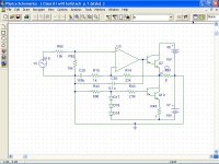
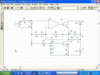
Attachments
This amp sounds pretty good. The treble is not to **** hot, a cymbal doesn't sound like a cymbal, but the rest is all good.
You will all laugh your butts off when you read here what I used for parts:
Op-amp: LM741
Transistors: TIP 120
Thats all I could get at work. I think I will look for better parts from Digikey and try building it again. Then I will try to build a voltage stage with transistors and the like.
You will all laugh your butts off when you read here what I used for parts:
Op-amp: LM741
Transistors: TIP 120
Thats all I could get at work. I think I will look for better parts from Digikey and try building it again. Then I will try to build a voltage stage with transistors and the like.
I'm also sure it will sound a bit better when the FB capacitor is reduced!
Furthering Chris' suggestions, how about an LF356? Tame enough, fast, cheap. Or a TL071...
Cheers!
Clem
ps: one other thing - if you do switch to a faster op-amp (uh, what opamp isn't faster than a 741 these days...), don't forget putting bypass capacitors (0.1uF) from each supply rail to ground - near the op-amp.
Hi Clem,
I was thinking of output drive capability too. Your suggestions may do it as well. The NE5534A does have a good sound.
And yeah. Almost anything is faster than a 741 type at 0.6 V/uS. I'm trying to figure out how bad things are to get a 741 to oscillate. The feedback cap should have been much smaller as you have pointed out.
-Chris
I was thinking of output drive capability too.
Your suggestions may do it as well. The NE5534A does have a good sound.And yeah. Almost anything is faster than a 741 type at 0.6 V/uS. I'm trying to figure out how bad things are to get a 741 to oscillate. The feedback cap should have been much smaller as you have pointed out.
-Chris
Hi Chris,
Good point!
Things would have to be pretty bad for a 741 to complain - something like heavy capacitance at the output, or unstable power supply, or bad grouding... - Eva's suggestion of putting in series resistors would be a good idea to decouple the op-amp a bit?
Cheers!
davidallancole,
Maybe it's time to have a good look at your grounding as well!
- Status
- This old topic is closed. If you want to reopen this topic, contact a moderator using the "Report Post" button.
- Home
- Amplifiers
- Solid State
- Oscillation