Hi ! I am trying to built Anthony Holtons 400 W symmetrical amp.
I'm currently in the Pre-flight test, and..yes there is smoke.
I used the 17.2.2004 Revised Schematic. The 100 Ohm R32 and R15 (Emitter of two MJE350) resistors start smoking....
I ve searched the forum but did not find any similar problem. Is there any possibility of 2 destroyed MJE350s. I would be very thankfull for any help!
Another question about this schematic: is R42 really 1 milli ohm?
Thank you alot !
Mat.
Well ... about R42 ... deffiniyely no - if you apply the Ohm's law it appears that 600A current flows there when the transistor Q20 is on. (I=U/R which means I=0.6V/0.001Ohm=600A).
Now about the smoke. Mind that I haven't tried this amp so I can only guess what the problem is. As far as I calculated something like 20mA should flow through these resistors. This current would not damage a 0.25W 100 Ohm resostor. The problem may be with the MJE-s - you may unmount them and measure them with an ohmmeter. Another possible reason - too high voltage on their bases (that would result in higher emiter voltage and obviously - higher current) - be sure to check weather you have mounted all the elements on the PCB correctly. I had a problem like that - I found that I hadn't connected the negative feedback propperly. You may also check weather the input differential amp is ok including the current generator (Q1 and the elements around) because if the current through R3 and/or R5 is larger than it should be the voltage on this/these resistors will be too large and this voltage is the input voltage of the MJE-s. Another problem I have had with my prototypes are the current mirrors (Q7, Q9). The transistors should have equal parameters (especially the BE-voltage).
In my oppinion start with checking the PCB and mounting.
I will remind you that I have not personal experience with that amp and can only give you some ideas. I hope I was helpful. Share what the result of tests is. Good luck") !
!
Now about the smoke. Mind that I haven't tried this amp so I can only guess what the problem is. As far as I calculated something like 20mA should flow through these resistors. This current would not damage a 0.25W 100 Ohm resostor. The problem may be with the MJE-s - you may unmount them and measure them with an ohmmeter. Another possible reason - too high voltage on their bases (that would result in higher emiter voltage and obviously - higher current) - be sure to check weather you have mounted all the elements on the PCB correctly. I had a problem like that - I found that I hadn't connected the negative feedback propperly. You may also check weather the input differential amp is ok including the current generator (Q1 and the elements around) because if the current through R3 and/or R5 is larger than it should be the voltage on this/these resistors will be too large and this voltage is the input voltage of the MJE-s. Another problem I have had with my prototypes are the current mirrors (Q7, Q9). The transistors should have equal parameters (especially the BE-voltage).
In my oppinion start with checking the PCB and mounting.
I will remind you that I have not personal experience with that amp and can only give you some ideas. I hope I was helpful. Share what the result of tests is. Good luck
!Hi ! Thank you alot for the fast reply !
I am not at home at this time.
I found a link to an older version of the construction plans :
http://www.newton-lab.ru/files/symamp.pdf
I downloaded mine from Anthony's old web site 2 years ago.
As soon as I get home I will post a pic of the pcb layout (self made)
I think I must give it a thorough look for any mistakes.
Then I will measure the MJE's
Thanks! Mat.
Good news!
After the 3d check I noticed that I had soldered all four Q2-Q5 in wrong direction! shame on me !!!
After the repair everything seems to be working properly. Only at R3,R5 I measure 1.45 instead of 1.6 V.. I hope it's ok !
Now I have to get me the insulation washers for the mosfets.
Maybe tomorrow I can try this amp out!
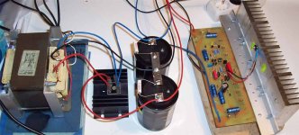
Attatched there is a picture of how it looks right now
The transformator is a 1000VA transformator from a defect microwave oven. I made new secondary windings acording to the core size. It was a temp class H transformator. I hope it won't get too hot. the problem right now is the extremly loud buzz. I hope that by welding it back together and by fixing the windings with epoxy it will not buzz anymore. In case it affects the sound I will then buy a toroidal.
Thank you again very much for the help ! Mat.
After the 3d check I noticed that I had soldered all four Q2-Q5 in wrong direction! shame on me !!!
After the repair everything seems to be working properly. Only at R3,R5 I measure 1.45 instead of 1.6 V.. I hope it's ok !
Now I have to get me the insulation washers for the mosfets.
Maybe tomorrow I can try this amp out!
Attatched there is a picture of how it looks right now
The transformator is a 1000VA transformator from a defect microwave oven. I made new secondary windings acording to the core size. It was a temp class H transformator. I hope it won't get too hot. the problem right now is the extremly loud buzz. I hope that by welding it back together and by fixing the windings with epoxy it will not buzz anymore. In case it affects the sound I will then buy a toroidal.
Thank you again very much for the help ! Mat.
Attachments
 ))
))Glad to hear that
!The problem with R3 and R5 does not seem to me so serious - just in case you should probe the zener voltage, the values of R8, R3 and R5 - tolerance of elements is perhaps what causes this difference in voltage. Otherwise you should take some care of what happens wrong.
- Status
- This old topic is closed. If you want to reopen this topic, contact a moderator using the "Report Post" button.
- Home
- Amplifiers
- Solid State
- HELP NEEDED: 400W symmetrical amp