Hi,
after a small chat in Suzy thread, ETI 5000 MOSFET Power amp, I posted a link to a schematic from Dr Bora on his Delta amplifier which is quite unusual at least in that sense it uses in audio gear a very seldom seen "Cross Quad" diff pair at the IP.
That led me to start this thread as I wanted to know if other have seen and/or used it, and bring it out in the light.
At a first look it cheats one's eyes as it doesn't behave as "expected" with a normal diff pair, it has actually an inverted output in comparison to the "normal" diff pair.
Analog Devices shows an exampel of the cross quad in their datasheet for
MAT04 which starts on page 8 with a shematic seen on p.9, though with an additional diff pair on top which in this case acts as the input.
Dr Bora's Delta amplifier schematic can be seen here.
Your thought's and experiences?
Cheers Michael
Ultima Thule said:At a first look it cheats one's eyes as it doesn't behave as "expected" with a normal diff pair, it has actually an inverted output in comparison to the "normal" diff pair.
Not as far as I can see in the Delta schematic...
It should also work with MOSFETs, but most simulators have problems with it, sop i guess it's back to the old 'build it and see' ways
")
Ask directly dr Jagodic whether he built it and if so, how does (n't) it work.
I'm interested....
About croos-quad... I have not used it, I don't see many advanteges, but one huge disadvantage- possible saturation of some of input bjts at clipping/slew overload.
Look to Hawkford's site for more info.
regards
I'm interested....
About croos-quad... I have not used it, I don't see many advanteges, but one huge disadvantage- possible saturation of some of input bjts at clipping/slew overload.
Look to Hawkford's site for more info.
regards
The strange thing is... I started to doubt.... and simmed just as author drawn it and it simmed (1kHz) flawlessly with both 'positive' and 'negative' feedback...
unless fed with a sqare, than the original design showed oscillations at some 8MHz
Great mistery to me
I think this can have something to do with saturation of cross-quad and changed polarity of inputs (TL071 style), but I don't know.
The only 'rational' explaination is the simulator gets fooled by kind of classD work of some stages with high carrier frequency... and it is not visible in sim.
So this actually could work, that's why I would be interested.
very interested
regards
Adam
Ok,
I see...
Because when I look at the cross quad I do understand why it get's inverted at it's output, hmm.. does it behave differently for small signals compared to large signals?
Adam, did you sim just the cross quad alone, it would be best to just isolate it for now and study it, if I find the time I will build it tomorrow Friday.
Thanks for your input,
Cheers Michael
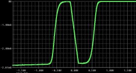
Ultima Thule said:does it behave differently for small signals compared to large signals?
Exactly
horisontal is difference voltage and the curve is collector current of one output 'legs'.
So sometimes it can work provided never switched to different 'monotonics' part of the curve, which can happen only in noiseless/clipless/TIMless simulators.
I guess it deserves further investigation.
cheers
Attachments
How does it work?  My eye sees a positive feeback loop around Q3 and Q4, actually I see positive feedback into both the base and emitter of both Q3 and Q4.
I tried simming it, it works fine in small signal analysis, but in .tran it quickly latches up and acts like a normal LTP.
My eye sees a positive feeback loop around Q3 and Q4, actually I see positive feedback into both the base and emitter of both Q3 and Q4.I tried simming it, it works fine in small signal analysis, but in .tran it quickly latches up and acts like a normal LTP.
The circuit seems very touchy . Q1 is working as an emitter follower. Q2 is the gain stage and Q3 runs in coomon base.
As Q2 turns on more. Q4 turns off and Q1 also acts as a common base stage. This is why the current in Q1 decreases as the base goes more positive. So this is positive feedback but not enough to oscillate.
The circuit simulates as being much more linear than the LTP with far more abrupt limiting
As Q2 turns on more. Q4 turns off and Q1 also acts as a common base stage. This is why the current in Q1 decreases as the base goes more positive. So this is positive feedback but not enough to oscillate.
The circuit simulates as being much more linear than the LTP with far more abrupt limiting
Attachments
The cross quad LTP is just a low part count version of this, I think:
It's a darlington LTP with the inner transistors cascoded to operate at a fixed 0.7V Vce. However, the collectors of the outer transistors are cross-connected to the load resistors and this ruins the gain and phase characteristics at high frequencies because the base currents of the inner transistors contribute to the wrong output leg (a plain darlington would behave better).
I don't see any advantage in that circuit other than part count reduction, because the higher gain, the 2nd order roll-off and the cumbersome latch-up are absolutely undesirable characteristics. We all have been adding degeneration resistors to our LTPs for a long time now in order to reduce their gain, so why would it seem attractive to add 30dB of gain now?
An externally hosted image should be here but it was not working when we last tested it.
It's a darlington LTP with the inner transistors cascoded to operate at a fixed 0.7V Vce. However, the collectors of the outer transistors are cross-connected to the load resistors and this ruins the gain and phase characteristics at high frequencies because the base currents of the inner transistors contribute to the wrong output leg (a plain darlington would behave better).
I don't see any advantage in that circuit other than part count reduction, because the higher gain, the 2nd order roll-off and the cumbersome latch-up are absolutely undesirable characteristics. We all have been adding degeneration resistors to our LTPs for a long time now in order to reduce their gain, so why would it seem attractive to add 30dB of gain now?
It is different from the darlington LTP because the emitter follower/cascode that drives the base of the other side, carries current of the opposite side driving it. So it has Vbe that varies opposite to the Vbe variation of the diffpair transistors.
In other words the Vbe's of the emitter followers adjust slightly to predistort the signal that goes in to the emitter coupled pair. This enhances linearity.
It seems like a really elegant solution, would work with enhancement mode MOSFETs just as well, to reduce input stage nonlinearity, and MOSFETs wouldn't suffer the saturation/reverse operation problem when overdriven that can cause latchup.
mirlo said:
It seems like a really elegant solution, would work with enhancement mode MOSFETs just as well, to reduce input stage nonlinearity, and MOSFETs wouldn't suffer the saturation/reverse operation problem when overdriven that can cause latchup.
That was exactly what I wrote about in my post. Unfortunately, simulating it with the MOSFET models I have at hand is even more touchy than with BJTs. Also, if you use all the same MOSFETs in tbe simulator (impossible in real life, of course), the simulated distortion goes down to the order of the sim numeric error
davidsrsb said:Not really
At audio frequencies the input transistors collector currents are nearly constant and modulating the bases of the output transistors has little effect.
At RF nothing is constant and base currents are no longer negligible in comparison with collector currents. Good routing of base currents makes the defference between poor and good stability.
mirlo said:It is different from the darlington LTP because the emitter follower/cascode that drives the base of the other side, carries current of the opposite side driving it. So it has Vbe that varies opposite to the Vbe variation of the diffpair transistors.
In other words the Vbe's of the emitter followers adjust slightly to predistort the signal that goes in to the emitter coupled pair. This enhances linearity.
It seems like a really elegant solution, would work with enhancement mode MOSFETs just as well, to reduce input stage nonlinearity, and MOSFETs wouldn't suffer the saturation/reverse operation problem when overdriven that can cause latchup.
MOSFETs would require both transconductance and Vgs matching in 4 devices, this is not a trivial task at all.
I think darlington-like approach still wins:
An externally hosted image should be here but it was not working when we last tested it.
This works the same or better provided that the model of PNP and NPN devices is chosen to have similar transconductance around 1mA. Furthermore, the current mirrors with high value resistors work only for audio frequencies and roll off quickly at RF, thus improving phase margin. As a bonus, this circuit should not suffer from latching or phase reversal issues, altough turn-on after a overdrive period relies on leakage currents and positive feedback, so it may probably take some hundreds of nanoseconds. Two additional 1uA current sources may be added to ensure class A operation of the PNP devices and proper recovery after overdrive.
Note that ultra-precise current sources are not required, because what matters here are just current slopes.
A funnier version:
It should be also latching-free and phase-reversal free. The four lower transistors and their emitter resistors would require some matching for best results, though.
An externally hosted image should be here but it was not working when we last tested it.
It should be also latching-free and phase-reversal free. The four lower transistors and their emitter resistors would require some matching for best results, though.
For the version with the PNP emitter followers, it looks like you might need another output leg on the current mirrors on top to actually have an output (?)
I have a bad habit of presuming matching is no problem.
Does anyone make monolithic MOSFET arrays? Like MAT-04 except MOS?
I have a bad habit of presuming matching is no problem.
Does anyone make monolithic MOSFET arrays? Like MAT-04 except MOS?
- Status
- This old topic is closed. If you want to reopen this topic, contact a moderator using the "Report Post" button.
- Home
- Amplifiers
- Solid State
- The Cross Quad diff