Stuart,
Thanks for your reply ... Thats was I thought ... I've built tube stuff in the past, but rarely touch SS stuff.
I've heard that lateral mos-fet does not have to be that well matched in a set ?
I have 8 Hitachi K176 and 8 J56 - I believed that are graded and matched by the seller.
I'm going to put them in a Counterpoint SA20 Chassis using Denis Output stage and I have an Aikido board octal board stuffed for 12SL7 and 12SN7.
I was wondering if the Mosscode front end would be able to drive 10 each npn and pnp transistors? I have an Adcom 565 with a bad input board. I would very much like to tube it.
The DC rails are 83+-vdc. I have also thought about tubing my Adcom 545 with the mosfit outputs rated a 100wpc.
Thanks
Ben
The DC rails are 83+-vdc. I have also thought about tubing my Adcom 545 with the mosfit outputs rated a 100wpc.
Thanks
Ben
Member
Joined 2009
Paid Member
I was wondering if the Mosscode front end would be able to drive 10 each npn and pnp transistors? I have an Adcom 565 with a bad input board. I would very much like to tube it.
The DC rails are 83+-vdc. I have also thought about tubing my Adcom 545 with the mosfit outputs rated a 100wpc.
Thanks
Ben
Based on my understanding, Yes, the Moscode front end should have low enough output impedance to drive a transistor output stage but distortion may be lower if you add in some driver transistors to further buffer the tubes from the power devices.
Hi,
I know it's been a long time since the last post in this thread but I hope someone will help me.
I am trying to build some kind of mosfet power amp for a guitar tube preamp based on the Matchless Hot Box (which is already running) to drive a 100~150W 4x12" cabinet.
In this thread there are some interesting ideas which I have compared with other desings like the Marshall Mosfet Twin Reverb power amp (I own one which sounds quite good for me), but there is a problem with all them: 2SJ49s and 2SK134s mosfet are really expensive.
I found a Chinese guy on this forum who sells them for 28$ per pair plus shipping costs. Does it worth paying this money or is there any other mosfet with similar performances?
Any suggestion will be welcome.
Thanks,
Miquel
Hi, forum.
I was wondering why it's so hard to find DIY projects of tube/mosfet hybrid amp. Is it because hybrid stuffs cannot make better sound than all-tube or all-solid-state stuffs? What I would like to build is the one using tubes at input stage and solid-state (probably mosfet) at output stage. Any idea, experience or link to a website?
Thanks.
I've looked and built a hybrid prototype - and have this to add
1) The biasing of the solid state should NOT rely on the tube.
2) I've read the tube and solid state circuitry should only be AC coupled.
3) A high voltage tube power supply is needed + the solid state supply.
In the end, I've come to the conclusion that its best to have a tube preamp ==> MOSFET power amp.
.
Member
Joined 2009
Paid Member
I'm sorry about my ignorance but don't know what a power-LTP is (as a Spaniard I m really bad at English acronyms). Cheer up! try to remember that name, please...Wavebourn wrote thousands of postsWavebourn has a really interesting option for SS output that is some kind of power-LTP - I think it's worth looking at. Just can't remember the darn name of it...
 .
.Thanks,
Miquel
Sepolansky,
Sorry for the late reply. Been busy... Yes, it can be applied to the DH500 as well. The only difference between the the DH500 and the DH200/220 is the larger voltage on the output stage and of course the fact that the 500 has 6 MOSFETs per channel.
From what I see in pictures, you have a little extra room in the DH500 for mounting a plate w/ tube sockets and the few resistors/caps needed. I was looking for a 500 on eBay, - but they seem to fetch rather high prices relative to a blown DH200
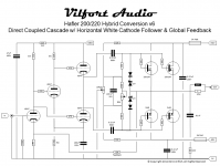
I have been refining the circuit a bit and changed values of some of the resistors. Broskie published a great article on the white cathode follower here: The Tube CAD Journal, August 1999 pg 1 In it (see page 4) he concludes that the plate load resistor of the top tube in the white cathode follower circuit should be Ra = rp/mu.
That seemed easy enough for the 6SN7 http://www.hifitubes.nl/weblog/wp-content/tung-sol-6sn7.pdf : 7,700/20 = 385 ohm. So a 390 ohm resistor would do nicely. To balance the circuit ala Aikido, I went for 390 ohm on the cathode of the bottom triode as well.
I have attached the updated schematic. Works like a charm and sounds very good too. Lots of detail. I now hear layers of instruments I newer heard before... With a DH500 you would have lots of power too.
Please share your findings as your project progresses.
D.
The value of Ra for white cathode follower depends on what load is the white cathode follower driving. At Tube CAD Journal you can find this formula for Ra: "Ra = (rp + 2RL)/mu"
link: "http://www.tubecad.com/2006/10/blog0083.htm"
Actually I think this circuit would sound alot better when operated in class A. I have my doubts about performance of class AB open-loop stage with just two parallel mosfets.
Improved Tube/MOSFET circuit
This post was a little older. The evolution of this amp eventually led to using a bit of (oh no!) global feedback. As you can see from the schematic, this is now a modified white cathode follower running in class A. The power bandwitdh goes to 200Khz with a single pair of MOSFETS and to 60KHz with 3 pair.
This post was a little older. The evolution of this amp eventually led to using a bit of (oh no!) global feedback. As you can see from the schematic, this is now a modified white cathode follower running in class A. The power bandwitdh goes to 200Khz with a single pair of MOSFETS and to 60KHz with 3 pair.
Attachments
Thanks Denis,
I appreciate the input. I like the simplicity of the solid state portion of your circuit, the lack of global feedback and your choice of octals. While
I haven't gotten my own project to one of the front burners yet, I hope to soon.
While Broskie did "prove" the Ra = rp/mu, he seems to have ignored it in some of his subsequent circuits, something I found a bit odd. No question, the guy is a genius, and I'm sure we're all grateful for his shared insights.
I wonder about a few options, the choices you made and what sonic differences you may have heard if you played with different voltage gain circuits. Specifically, the 6SL7 in current source loaded form, did you try any other tubes here? The gain is very high and so is Cg-p, so I wondered about HF rolloff. I thought perhaps another tube, even with a cascode depletion MOSFET CCS might serve well. In the White Follower, while the 6SN7 is a very fine sounding tube, I wondered why you chose it over something like a higher gm, higher current tube such as a 6H30 or ECC99. Either of those would seem to provide more drive to overcome the input capacitance of the MOSFETs. That's something very much on my mind with 3 pair to drive.
In the output stage, I noticed no additional capacitance to equalize the n-channel and p-channel devices. SS is not my forte, so please forgive my ignorance, if such equalization is not needed in your circuit.
I plan to build two of these beasties; each of my (Tympani) bass panels is 8 ohms. I separately wired them, so I can drive them individually, in series for 16 ohms (if I do an OTL!), or in parallel for 4 ohms as the factory did. So, each channel of a DH500 will drive one 8 ohm panel.
Thanks again, Denis, this may be the circuit I needed to bring the bass impact to my system.
I promise to post progress and results as I get this under way, even if my building skills are eerily reminiscent of a third grader with a hacksaw and dull drill bits.
Stuart
Hi Stuart, did you ever get this project off the ground? I have a DH-500 that needs new driver boards. I'd love to go with tubes and like the way you and Dennis are thinking. I'm not a EE and want to get the circuit right.
thanks!
The value of Ra for white cathode follower depends on what load is the white cathode follower driving. At Tube CAD Journal you can find this formula for Ra: "Ra = (rp + 2RL)/mu"
link: "http://www.tubecad.com/2006/10/blog0083.htm"
Actually I think this circuit would sound alot better when operated in class A. I have my doubts about performance of class AB open-loop stage with just two parallel mosfets.
What changes would need to be made to get the circuit into Class A?
What changes would need to be made to get the circuit into Class A?
I was referring to circuit in post #72. To make the output run in class A mode, you need to raise the idle bias to cca 1A - 1.5A. Obviously, this will generate lots of heat and demands better PSU for lower ripple.
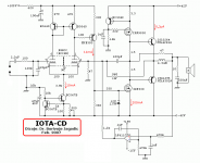
If you are interested in hybrid circuit I recommend you this one.
http://www.diyaudio.com/forums/solid-state/195351-80w-hybrid-audio-amplifier.html
http://bas.elitesecurity.org/IOTA-CD.html
Attachments
Hi Stuart, did you ever get this project off the ground? I have a DH-500 that needs new driver boards. I'd love to go with tubes and like the way you and Dennis are thinking. I'm not a EE and want to get the circuit right.
thanks!
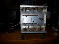
Wow, it's been a long time. Life changes forced me to pay attention to other things, but yes, I did get this off of the ground.
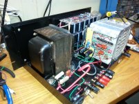
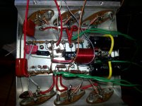
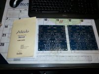
The design ended up being a multi-chassis solution. Two DH500's equipped with DIN connectors for inputs, Two Aikido chassis and one Aikido power supply chassis.
The Aikido chassis are made, one almost complete. Haven't yet started the power supply chassis stuffing, although the chassis is built (wood frames with plastic tops.
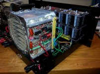
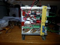
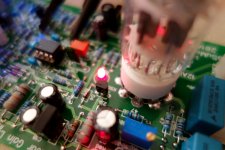
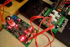
One DH500 is complete. It is an output stage and power supply only now.
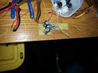
Pictures and schematic attached. I hope it works!
I'll post more of this come spring, when I hope to get back to it.
Stuart
Attachments
-
Corrected-Hafler500--source_R.pdf13.3 KB · Views: 172
-
 20131106_220446.jpg754.8 KB · Views: 615
 -
 20131106_220457.jpg661.6 KB · Views: 573
 -
 20131011_175914.jpg485.8 KB · Views: 170
 -
 20131014_044516.jpg801.4 KB · Views: 195
 -
 20131021_051905.jpg740.6 KB · Views: 206
 -
 20131021_051833.jpg647 KB · Views: 514
 -
 20131108_113626.jpg650 KB · Views: 212
That's very cool Stuart. Definitely update us as things progress.One DH500 is complete. It is an output stage and power supply only now.
Pictures and schematic attached. I hope it works!
I'll post more of this come spring, when I hope to get back to it.
Stuart
That's very cool Stuart. Definitely update us as things progress.
Thank you Mark, will do!
If somebody is interested, see this post for the final schematics / measurements:
TubSuMo as built
Gerbers, PCBs are available. There is even one set fully assembled / tested IPS + OPS boards for sale (2 channels set)
Great sounding amp! Let me know if you will have questions.
TubSuMo as built
Gerbers, PCBs are available. There is even one set fully assembled / tested IPS + OPS boards for sale (2 channels set)
Great sounding amp! Let me know if you will have questions.
Attachments
- Status
- This old topic is closed. If you want to reopen this topic, contact a moderator using the "Report Post" button.
- Home
- Amplifiers
- Solid State
- reliable tube/mosfet hybrid amp