I think i saw somebody asking for this")
I have that schematic too but it just doesn't look right in the bias\offset adjustment network area.
I have that schematic too but it just doesn't look right in the bias\offset adjustment network area.
Hey Amp Guy,
Which Schematic are speaking of? The OTL1 schematic that only shows the amp side but not the regulated PS side? Can you post what you have? Thx!! I just picked up a OTL1 from California and I need all the info I can find to repair it.
No. I Have Minni A7's
I love the sound of A7's from Altec-Lansing.
I purchase these beautiful 6" woofers from Parts Express. Purchase a set of Goodman horn tweeters at a swap meet.
Built a 16db two way crossover.
Built a reduced A7 enclosure around the 6" woofers and horns.
That's it.
Take Care
Ivey
I love the sound of A7's from Altec-Lansing.
I purchase these beautiful 6" woofers from Parts Express. Purchase a set of Goodman horn tweeters at a swap meet.
Built a 16db two way crossover.
Built a reduced A7 enclosure around the 6" woofers and horns.
That's it.
Take Care
Ivey
Hey Amp Guy,
Which Schematic are speaking of? The OTL1 schematic that only shows the amp side but not the regulated PS side? Can you post what you have? Thx!! I just picked up a OTL1 from California and I need all the info I can find to repair it.
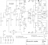
Oops sorry I was reffering to the moscode 300 schematic that has been circulating around .
there is also a hybrid using hitachi mosfets in the Audio Amateur
(1989 issues 1 and 2)
Moscode schematic
Amp-guy: The Moscode 300 schematic that is circling around does indeed look a bit fishy. First, the 1M resistors coming from the BIAS network are not connected to get gates of the MOSFETs. That is easy to spot.
Then there is the ambiguous 6.8K 39K notation on the resistor that goes to B+ and B- respectively. Looking at the diagram, my bet would be that right value is 39K. The BIAS voltage gate to gate is normally in the 0.8V to 1.4V depending on how hot you want to idle the amp. So start by turning trim pot P2 all the way over. This should give us close to 0V across P2. Then slowly turn P2 until the desired BIAS
There are a few other things that I do not care for: the overload zener diodes in the VAS tube section can be omitted. And the odd diode/cap arrangement at the output of the white cathode follower needs to go as well (overload or tube breakdown protection? – I am not sure was the intent was here. It is an AC circuit shunting the signal via the 470 ohm to the B+/- via two diodes…).
Here is a cleaned up version of the Moscode schematic.
Attachments
Does anyone know why the counterpoint design is so prone to go volcanic?
My hunch is that there is not adequate protection from exceeding the gate breakdown voltage on the mosfets. I have severely abused Hitachi mosfets and never had a failure and many others have had the same experience.
so what gives?
My hunch is that there is not adequate protection from exceeding the gate breakdown voltage on the mosfets. I have severely abused Hitachi mosfets and never had a failure and many others have had the same experience.
so what gives?
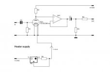
Well, i made this amp about a year ago, i didn´t finish the protection circuit until now. I like it´s sound very much, it sound beter than my denon and my old 15w tube amp.The idle current is hi, 1A for maximum output current about 7A (i use 4 ohms speaker), so at low volume i hear a class a amp. I used very large heatsink, and here in brazil at hot days, the mosfets run at 70ºC. I don´t have any picture here, i´ll send one soon.
The output impedance is 0.17 ohms e -3db response from 2hz to 220khz and the distortion o coudn´t measure, may audio generator is really bad.
I think if it´s working for a year in a bad conditions, it´s realible, the schematic is simple, 2 small tubes, 2 mosfets, a current sink and a current mirror. The only thing i don´t like i still have one capacitor in the signal path, but it´s small and a good one is not so expensive.
Good luck for all
View attachment hibrido.pdf
Folks,
On one side, the sonics are often quite what they promised to be (especially when using a lot of mosfets - the parasitic capacitances just about kill any tube driving circuit - bipolars are a much better choice) and at times relaibility can be iffy.
I have recently adapted the kind of "current dumper" concept from people like Quad and others to Tube Amplifiers. The little whitepaper on that contains a few notes on other hybrids too:
http://www.diyhifisupply.com/files/Fusion%20Whitepaper.pdf
Hopefully I will soon be able to show a simple DIY Hybrid that uses the Fusion Module and the Universal Tube Stage from Diy HiFi Supply | Take Control.
This would a very easy DIY Amp, with around 40/60W into 8/4 Ohm.
Ciao T
I was wondering why it's so hard to find DIY projects of tube/mosfet hybrid amp.
On one side, the sonics are often quite what they promised to be (especially when using a lot of mosfets - the parasitic capacitances just about kill any tube driving circuit - bipolars are a much better choice) and at times relaibility can be iffy.
I have recently adapted the kind of "current dumper" concept from people like Quad and others to Tube Amplifiers. The little whitepaper on that contains a few notes on other hybrids too:
http://www.diyhifisupply.com/files/Fusion%20Whitepaper.pdf
Hopefully I will soon be able to show a simple DIY Hybrid that uses the Fusion Module and the Universal Tube Stage from Diy HiFi Supply | Take Control.
This would a very easy DIY Amp, with around 40/60W into 8/4 Ohm.
Ciao T
How About the Lazarus Hybrids
Lazarus was an outfit near or in Hollywood CA back in the early 90's that made a few different Hybrid amps including a Class A stereo 50 watter. Sounds great, am using it to drove my Quad 63's.
Anyone know anything about that company? Would love a schematic.
THANKS
Charles
Lazarus was an outfit near or in Hollywood CA back in the early 90's that made a few different Hybrid amps including a Class A stereo 50 watter. Sounds great, am using it to drove my Quad 63's.
Anyone know anything about that company? Would love a schematic.
THANKS
Charles
Hi, forum.
I was wondering why it's so hard to find DIY projects of tube/mosfet hybrid amp. Is it because hybrid stuffs cannot make better sound than all-tube or all-solid-state stuffs? What I would like to build is the one using tubes at input stage and solid-state (probably mosfet) at output stage. Any idea, experience or link to a website?
Thanks.
Its pretty simple, just bolt a valve stage on the front end of a class AB amp and reduce the amps gain to adjust for the valves gain.
I designed my own and used an 12AU7 SRPP front end with class AB amplifier with its gain reduced to 3. Sounds very clean. So you get a bit of valve warmness with the power of solid state.
Here is a good example. Sounds silly fantastic! - Can be built out of an old HAFLER or Counterpoint - or from scratch. Ballsy basss and very detailed! Thanks MOSCODE
Thank you!!!!!!!
More Hafler tube/MOSFET
Sepolansky,
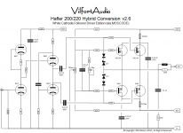
Sorry for the late reply. Been busy... Yes, it can be applied to the DH500 as well. The only difference between the the DH500 and the DH200/220 is the larger voltage on the output stage and of course the fact that the 500 has 6 MOSFETs per channel.
From what I see in pictures, you have a little extra room in the DH500 for mounting a plate w/ tube sockets and the few resistors/caps needed. I was looking for a 500 on eBay, - but they seem to fetch rather high prices relative to a blown DH200. So I have not tried yet... But looks very doable.
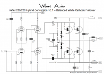
I have been refining the circuit a bit and changed values of some of the resistors. Broskie published a great article on the white cathode follower here: The Tube CAD Journal, August 1999 pg 1 In it (see page 4) he concludes that the plate load resistor of the top tube in the white cathode follower circuit should be Ra = rp/mu.
That seemed easy enough for the 6SN7 http://www.hifitubes.nl/weblog/wp-content/tung-sol-6sn7.pdf : 7,700/20 = 385 ohm. So a 390 ohm resistor would do nicely. To balance the circuit ala Aikido, I went for 390 ohm on the cathode of the bottom triode as well.
I have attached the updated schematic. Works like a charm and sounds very good too. Lots of detail. I now hear layers of instruments I newer heard before... With a DH500 you would have lots of power too.
Please share your findings as your project progresses.
D.
Sepolansky,
Sorry for the late reply. Been busy... Yes, it can be applied to the DH500 as well. The only difference between the the DH500 and the DH200/220 is the larger voltage on the output stage and of course the fact that the 500 has 6 MOSFETs per channel.
From what I see in pictures, you have a little extra room in the DH500 for mounting a plate w/ tube sockets and the few resistors/caps needed. I was looking for a 500 on eBay, - but they seem to fetch rather high prices relative to a blown DH200
. So I have not tried yet... But looks very doable.I have been refining the circuit a bit and changed values of some of the resistors. Broskie published a great article on the white cathode follower here: The Tube CAD Journal, August 1999 pg 1 In it (see page 4) he concludes that the plate load resistor of the top tube in the white cathode follower circuit should be Ra = rp/mu.
That seemed easy enough for the 6SN7 http://www.hifitubes.nl/weblog/wp-content/tung-sol-6sn7.pdf : 7,700/20 = 385 ohm. So a 390 ohm resistor would do nicely. To balance the circuit ala Aikido, I went for 390 ohm on the cathode of the bottom triode as well.
I have attached the updated schematic. Works like a charm and sounds very good too. Lots of detail. I now hear layers of instruments I newer heard before... With a DH500 you would have lots of power too.
Please share your findings as your project progresses.
D.
Attachments
Sepolansky,
Sorry for the late reply. Been busy... Yes, it can be applied to the DH500 as well. The only difference between the the DH500 and the DH200/220 is the larger voltage on the output stage and of course the fact that the 500 has 6 MOSFETs per channel.
From what I see in pictures, you have a little extra room in the DH500 for mounting a plate w/ tube sockets and the few resistors/caps needed. I was looking for a 500 on eBay, - but they seem to fetch rather high prices relative to a blown DH200
I have been refining the circuit a bit and changed values of some of the resistors. Broskie published a great article on the white cathode follower here: The Tube CAD Journal, August 1999 pg 1 In it (see page 4) he concludes that the plate load resistor of the top tube in the white cathode follower circuit should be Ra = rp/mu.
That seemed easy enough for the 6SN7 http://www.hifitubes.nl/weblog/wp-content/tung-sol-6sn7.pdf : 7,700/20 = 385 ohm. So a 390 ohm resistor would do nicely. To balance the circuit ala Aikido, I went for 390 ohm on the cathode of the bottom triode as well.
I have attached the updated schematic. Works like a charm and sounds very good too. Lots of detail. I now hear layers of instruments I newer heard before... With a DH500 you would have lots of power too.
Please share your findings as your project progresses.
D.
Thanks Denis,
I appreciate the input. I like the simplicity of the solid state portion of your circuit, the lack of global feedback and your choice of octals. While
I haven't gotten my own project to one of the front burners yet, I hope to soon.
While Broskie did "prove" the Ra = rp/mu, he seems to have ignored it in some of his subsequent circuits, something I found a bit odd. No question, the guy is a genius, and I'm sure we're all grateful for his shared insights.
I wonder about a few options, the choices you made and what sonic differences you may have heard if you played with different voltage gain circuits. Specifically, the 6SL7 in current source loaded form, did you try any other tubes here? The gain is very high and so is Cg-p, so I wondered about HF rolloff. I thought perhaps another tube, even with a cascode depletion MOSFET CCS might serve well. In the White Follower, while the 6SN7 is a very fine sounding tube, I wondered why you chose it over something like a higher gm, higher current tube such as a 6H30 or ECC99. Either of those would seem to provide more drive to overcome the input capacitance of the MOSFETs. That's something very much on my mind with 3 pair to drive.
In the output stage, I noticed no additional capacitance to equalize the n-channel and p-channel devices. SS is not my forte, so please forgive my ignorance, if such equalization is not needed in your circuit.
I plan to build two of these beasties; each of my (Tympani) bass panels is 8 ohms. I separately wired them, so I can drive them individually, in series for 16 ohms (if I do an OTL!), or in parallel for 4 ohms as the factory did. So, each channel of a DH500 will drive one 8 ohm panel.
Thanks again, Denis, this may be the circuit I needed to bring the bass impact to my system.
I promise to post progress and results as I get this under way, even if my building skills are eerily reminiscent of a third grader with a hacksaw and dull drill bits.
Stuart
Can be built out of an old HAFLER or Counterpoint
Denis, Thanks for sharing !
This may be surprising, but I have a Counterpoint SA20 with a blown output stage. I also have a set of replacement Hitachi Mosfet for a Hafler XL600, this may be perfect way to get the counterpoint chassis to play music.
What is the part # for the zener and the diode in the output stage ?
I also curious about what Anatech does for his Counterpoint Repair and Mods.
quinnling,
I know I shouldn't speak for Denis, but I think any old 1N series diode should work fine, voltage depending. I just have a personal preference for nothing worse than a UF type (like a UF4007). For the 12V diode, that just protects the gate from excess differential voltage, so any 12V 1W or 5W zener should do just fine. Digi-Key and Mouser, etc. are your friends here.
The nice thing about using an existing amplifier is that so much fabrication, heat sink sizing, power supply, etc. is already done. Just strip the input stage, rewire the output stage and add the tube stage and power supply. I love the concept. Saves weeks of work and lots of money.
Man I wish I didn't have to work for a living. I'd get home and start on this right away.
Stuart
- Status
- This old topic is closed. If you want to reopen this topic, contact a moderator using the "Report Post" button.
- Home
- Amplifiers
- Solid State
- reliable tube/mosfet hybrid amp