Hi! So, I bought a pair of MOSFET monoblocks and said myself to share it here ") It is not high-end amp, but I think ratio money/quality is good.
It is not high-end amp, but I think ratio money/quality is good.
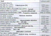
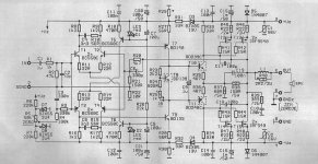
This is symetrical amp. with 120W/4Ohm output power. The amp, itself, has a differential amp. on input made of T1 to T4 with a current power sources T5 and T6 and LED diodes D1 and D2. Transistors T1, T2, T3 and T4 are coupled to system to make an output drift as small as it can. Using T7 and T8 is this system joined as driver for power transistors. Differential phase is powered by U lower approx. 13V (D3 and D4) for better behaviour during limitation (is in differential, not in end phase). Transistor T8 is screwed to heatsink with power mosfets to monitor its tempetature, which is transformed to idle current control. Resistors R37 and R38 sets power factor to 3. Null output U is set by R5, idle current by R25.
Constructing: Make sure NOT to remove or change + and - on LEDs (they are not for light!!!) (as I did...). This burn-out the outupt mosfets. (tested...). Avoid short circuit at output, not connected power source ground or only one pole. Amp dont has to have output load (but dont test it for a long time if U dont need it). Power resistors put approx. 5mm above PCB for output heat.
I didnt find any problems - except LEDs - because of I am an idiot... (why the hell they put LEDs on it - I dont need them, I have a LED on the box.... )
It is not high-end amp, but I think ratio money/quality is good.This is symetrical amp. with 120W/4Ohm output power. The amp, itself, has a differential amp. on input made of T1 to T4 with a current power sources T5 and T6 and LED diodes D1 and D2. Transistors T1, T2, T3 and T4 are coupled to system to make an output drift as small as it can. Using T7 and T8 is this system joined as driver for power transistors. Differential phase is powered by U lower approx. 13V (D3 and D4) for better behaviour during limitation (is in differential, not in end phase). Transistor T8 is screwed to heatsink with power mosfets to monitor its tempetature, which is transformed to idle current control. Resistors R37 and R38 sets power factor to 3. Null output U is set by R5, idle current by R25.
Constructing: Make sure NOT to remove or change + and - on LEDs (they are not for light!!!) (as I did...
). This burn-out the outupt mosfets. (tested...). Avoid short circuit at output, not connected power source ground or only one pole. Amp dont has to have output load (but dont test it for a long time if U dont need it). Power resistors put approx. 5mm above PCB for output heat. I didnt find any problems - except LEDs - because of I am an idiot... (why the hell they put LEDs on it - I dont need them, I have a LED on the box....
)Attachments
Hi,
what voltage is the voltage amp running on?
I am confused by the D3/4, R31/32 and R29/30 combination.
Is there voltage amplification in the final driver and common source stage?
The gate resistors seem very low at 15R. 100R upwards is more common.
Finally the red LEDs probably have about 1v8 across them. This gives about 1v2 across R18/19 generating about 2.5mA as an LTP tail current. This equates to about 1.2mA LTP currents and can be checked for balance by measuring the voltage drop across the emitter resistors R11 thro' R14. All should be about 27mV.
I would disconnect your speakers before doing this and maybe substitute a dummy load of 8r to 22r.
AndrewT said:Is there voltage amplification in the final driver and common source stage?
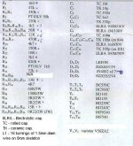
R38/R37 set gain of output stage.
150 Ohm/ 68 Ohm
Gain in output stage should be something like 3.
Looks like an elektor amplifier using IRF540 IRF9540.
Voltage is between 30 and 40V (symetrical)AndrewT said:Hi,
what voltage is the voltage amp running on?
- Status
- This old topic is closed. If you want to reopen this topic, contact a moderator using the "Report Post" button.
- Home
- Amplifiers
- Solid State
- 120W MOSFET amp.