I learned a "lot" in past two years and I`ve decided to design an amplifer from scratch...
so :
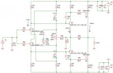
-What do you think about this amplifier I designed (just the spice-simulation-for now..)
-It is biased into class AB (100mA).
-is there a thermal runaway problem becouse of IRFP mosfets? If there is , then, how could I deal with it?
-The classic Vbe or Vgs multiplier is not a option becose I want to design fully simetrical amp!
-This amp could bi biased to run in class A, so what could be the output power with my power supply (+/-36V - 5A).
-the bias should be 2.5A?
Speaker load should be 4 Ohm.
so :
-What do you think about this amplifier I designed (just the spice-simulation-for now..)
-It is biased into class AB (100mA).
-is there a thermal runaway problem becouse of IRFP mosfets? If there is , then, how could I deal with it?
-The classic Vbe or Vgs multiplier is not a option becose I want to design fully simetrical amp!
-This amp could bi biased to run in class A, so what could be the output power with my power supply (+/-36V - 5A).
-the bias should be 2.5A?
Speaker load should be 4 Ohm.
Attachments
Interesting design, a bit like one of JLH's.
I think you will have a thermal problem with any output device other than lateral MOSFETs.
For class-a the max class-a power is determined by the amount of bias current (assuming voltage rails are high enough to drive that current into the load).
I think you will have a thermal problem with any output device other than lateral MOSFETs.
For class-a the max class-a power is determined by the amount of bias current (assuming voltage rails are high enough to drive that current into the load).

-adjusting VR2, you change collector voltages of q1 and q2, that`s how... (I`tried it in practice, not just a spice-simulation).
-Where should i put the diodes for teperature compensation?
-can you sand me schematic of symetrical multiplier?
-I`d like to hear wath ILIMZN and AKSA have to say about this idea?
thanks to everyone!
-Where should i put the diodes for teperature compensation?
-can you sand me schematic of symetrical multiplier?
-I`d like to hear wath ILIMZN and AKSA have to say about this idea?
thanks to everyone!
bogdan_borko said:1. adjusting VR2, you change collector voltages of q1 and q2, that`s how... (I`tried it in practice, not just a spice-simulation).
2. Where should i put the diodes for teperature compensation?
3. can you sand me schematic of symetrical multiplier?
4. I`d like to hear wath ILIMZN and AKSA have to say about this idea?
1. your solution is very original
you have chosen to not use any emitter resistors to help set bias
when C-E voltage of a transistor is lowered
the B-E voltage is gets higher to keep same current
When Q1/Q2 VBE gets higher, more bias in Q3/Q4
You use VR2 to reduce/increase collector voltage of Q1/Q2.
2. If you use Class A operation with a very large heatsink
you may get away without any temp compensation.
And this is of course the best.
If you need temp comp, then you could replace a bit of resistance R5/R6 with a temp sensing transistor.
Now is like 4 volt across R5, 220 Ohm.
Replace R5 with
BD139, used as a diode and mount it at heatsink, in series with 180 Ohm.
Do the same with R6 and another BD139.
Maybe put an 100uF cap across these sensors.
(BD139 could even be a VBE multiplier)
When the two BD139 gets hotter, will lower Gate-Source voltage and reduce current in output MOSFETS.
I think it may work,
as long as no serious unlinearity is introduced.
A single resistor, 220 Ohm, certainly is more linear.
You have a couple problems in that design...
First of all, it is easy to check for runaway in a simulator because you can set the simulated environment temperature. Typically this is 27 deg. C. There is a simulation setup menu somewhere for this, try to find it. Then try using 0 and 100 as temperatures, and check how your currents change.
Regarding runaway, there are two issues with your schematic. First of all, the bias setting is not confined to the output, but acts through the first stage, by setting it's bias current (or rather, attempting to do so but I will get to that later). This means that any change is amplified (gain) times, and relayed to tyhe output - which also means that ALL active elements would have to be thermally stabilised and matched. In principle, this is not an error, but a complication which needs carefull attention.
The basic topology is that of a current feedback diamond buffer. This at the very least means that your front end transistors (BJTs) whould ALL be thermally connected. This way you can at least attempt to stabilise them, but note I have said attempt. It is likely that this setup would only work if it was made on a monolythic IC or a close-spaced hybrid. With discretes, it will be problematic. There are many posts on the forum about practical diamond buffers (including one called 'diamond buffer eats transistors', which should make you think!), and in them you will see that in order to effectively tame the diamond buffer thermally (and also regarding oscillation), there is some degeneration in the output stage (emitter resistors). The bias current of the diamond buffer is determined solely by how well the B-E junctions of the first and second stage compensate, and act as current multipliers. Because the transistors are not perfect and have widely varying gains, you needs some way to normalize this using a well controllable and stable component, hence degeneration. This may not be as easy a I am describing it, but it will give you a pointer at what to look. Once the diamond buffer is stable, it is out of the equation thermally, and we can concentrate on the output stage.
Regarding the bias current setup, your setup should not work as drawn, for two reasons - since your J111 FETs are connected as current sources, no change of the bias pot should really change the current through them at all. The only way to change the current would be to make the current through the pot is lower than the one set by the Idss of the J111, then they operate in the triode area as nonlinear resistors. Even son no change should occur since varying the collector voltage of a BJT does not signifficantly (in an ideal BJT not at all) change it's collector current (otherwise we would never be able to make current sources with them!) unless we get outside the normal operating area, Vc < Vb. Hence, I don't see how you could vary the collector current by varying the collector voltage, considering Ic = Beta Ib, and Ib is set by R3 and R4, and power supply voltage.
Regarding the output stage, YES it will have runaway problems. You would likely only be able to make it work as is (assuming diamond buffer is thermally stable) with lateral MOSFETs.
In general, what you should look at, assuming that you have thermally stabilized the diamond buffer, is to design a clever bias generator for it, for instance, using a thermally dependent component - then you can chose that component to match the thermal co-efficient of your output MOSFETs (just be careful to include the gain of the circuit from bias generator to output into your calculations).
lineup said:
when C-E voltage of a transistor is lowered
the B-E voltage is gets higher to keep same current
Oh? How do we then manage to make constant current sources with them?
- Status
- This old topic is closed. If you want to reopen this topic, contact a moderator using the "Report Post" button.
- Home
- Amplifiers
- Solid State
- what do you think about this design?