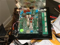
I am having a little trouble figuring out an M&K amp that I bought. It is pulled from a MX-100THX subwoofer and I was wondering about all the connections. The only connection that I can see from the back is the translucent connector in the top left hand corner.
I plugged it in, however the led on the front plate did not light up. I measured the voltage across the two terminals on the connector in the top left hand corner that comes from the power cord and through the fuse, which I am assuming that powers the amp which then makes the power LED to turn on. However, it seems that I am missing a module to make this work somehow? Does anyone know what I am missing?
Does anyone have any more info on this amp that can assist me in integrating this into my DIY project?
ANY info would be GREATLY appriciated.
For full size image please go to:
http://img62.imageshack.us/img62/5228/dscf20871ek.jpg
Attachments

You haven't passed AC voltages into the amp have you? If you did it will be toast.
There should be a transformer of a specific voltage along with rectifiers and electrolytic capacitors that provide DC voltage to get the amp working.
If all what you have is shown in the photo then your clearly missing these parts. You also need to know what size transformer you require to safely operate the amp and to extract its rated power output.
No, I have not passed any current into the circut at all.
Thats why I kinda knew that I was missing parts because the connector that I was talking about looks like it should plug into a power supply of some sort and that in turn plugs back into the board somehow.
Does anyone have a similar M&K subwoofer that can explain exactly what module I am missing and/or how it connects?
Thanks for your help so far
I have just recieved the additional parts that went to the amp, so now I am relieved...
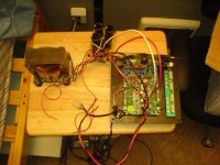
I am now faced with the task of connecting all the wires correctly. I have the power supply circutry that was mentioned before, as it is included in the picture. I have connected the square connector to the main board of the amp unit itself which fits correctly.
I am left with 2 pairs of thicker gauge wires (red & black) that I am assuming that leads to the two 12" woofers that this amp powered. I am left with supplying the power supply unit with 110v AC. I am assuming that the power lead connector (again the smaller plastic connector) to the caps and the transformer.
The two smaller red wires lead directly to the board with the caps and I am wondering if these are supposed to have the power supplied to them? If so, how can I tell which polarity I am supposed to hook them up to? I looked under the PCB containing the caps, and the right side is labeled "line" with a "+" and the left side is labeled "AC" with a "-" sign....
I hope that helps, if you need more pics, I can take them to clear everything up....
Thanks for your help!
Attachments
It sounds to me like the original transformer had dual secondary winding.
This is common as one supplies the amplifier section of the board and another (usually around 12v) supplies the protection circuitry.
I don't see a step down section so I assume this to be true. Its probably best if you get a second opinion as I'm barely qualified enough to be answering a question in the solid state forum.
- Status
- This old topic is closed. If you want to reopen this topic, contact a moderator using the "Report Post" button.
- Home
- Amplifiers
- Solid State
- M&K MX-100 amplifier