hi everyone
im trying to replace the output transistor of the design M250.. i will be using 2SA1302 an 2SC3281 instead of (MJI5024 and MJI1525)..also the output driver.. i will use C2344 and A1011 instead of (MJE1531 andMJE1530)...
i need your suggestion guys if it has an error in replacingthis transistors..
tnx a lot..
ryan jan")
im trying to replace the output transistor of the design M250.. i will be using 2SA1302 an 2SC3281 instead of (MJI5024 and MJI1525)..also the output driver.. i will use C2344 and A1011 instead of (MJE1531 andMJE1530)...
i need your suggestion guys if it has an error in replacingthis transistors..
tnx a lot..
ryan jan
Replacing transistors in an existing design with faster ones can cause instability, also 2SA1302 and 2SC3281 are mostly fakes as they are no longer in production from Toshiba. MJE15030/31 and MJ15024/25 are very good transistors.
Why do you want to replace them ? Availability ?
Mike
Why do you want to replace them ? Availability ?
Mike
Avoid 2SA1302 and 2SC3281. Not only they will be fakes, but you will have a very hard time mounting a TO-264 plastic case in place of a TO-3 metal-can case. (If you insist in using Toshiba, go for the newer 2SA1943 and 2SC5200 models.)
Despite their age, MJ1502x from On-Semi (Motorola) should be readily available as they are still industry-standard devices widely employed in audio power amplifiers. A better replacement may be the MJ2119x series, also from On-Semi. (Check also MJL1302 and MJL3281 if you want plastic cases).
Despite their age, MJ1502x from On-Semi (Motorola) should be readily available as they are still industry-standard devices widely employed in audio power amplifiers. A better replacement may be the MJ2119x series, also from On-Semi. (Check also MJL1302 and MJL3281 if you want plastic cases).
thanx guyzz!!
I planned to use 2SA1302 and 2SC3281 in 5 pairs all(10 all). and i am using it now for 2pairs only(for testing) and it seems their is something not good.. yes your correct mike..i forced to use it because its the only available. Is 2SA1943 and 2SC5200 also ok eva? the heatsink i used is designed and drill for this (2SA1302 and 2SC3281) transistors only thats why i am looking for good transitors that could fit into my heatsink and somelike the replacement of real M250 transistors..is there any available transistors that looks like 2SA and 2SC that could use for M250?.. i found that the real output transistors are different.
Thank you for the suggestions and comment guyz..
i also found out that there are so many fake with regards to 2SA1302 and 2SC3281.. but the one i used was bought by my father 5years ago..
By the way, can i chane the LED into zener diode?..i hav a 2.7-3.0volts available..
ryan jan..
2SA1943 and 2SC5200 were the new improved models that Thoshiba brought up when they discontinued 2SA1302 and 2SC3281 (I think it was in 1999), so they should work fine in place of the old devices.
MJL3281 and MJL1302 are custom versions of the old 2SA1302 and 2SC3281 made by On-Semiconductor and coming in the same package, their specifications differ a bit from those of the original devices (mostly due higher capacitances at the expense of better SOA), but they may be also good replacements.
Be careful because you may easily stumble into fakes of any of these models. Even the 2SA1302 and 2SC3281 bought 5 years ago could be fakes because they were already discontinued by that time, altough the fake market was not as big as nowadays.
guyzz!!
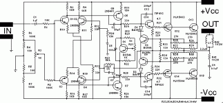
hey guyzz another replacing transistors to schematic diagram i got from here.. i plan to replace the 2N5401 and 2n5550 at the 2nd stage transistors into MJE340 and MJE350..it seems that transistors from 1st stage is the same from the 2nd stage.. Will it be ok if i replace it?..i got this design from here together with M250 and i use these two in our soundworks..
i need your suggestion guyzz...
Thank you..
Ryan Jan
Attachments

ryan,
If the replacement transistor's other characteristics (ft, hfe, hfe vs Ic, input capacitance) are about the same, then yes. It's improbably however that you'll be able to find something that has higher wattage and retains most of the other characteristics...
Why do you want to change the 2nd stage transistors anyway? Putting in higher-powered transistors there will not gain you any greater output power...
Cheers
thank you!!
i was thinking why this amplifier(2nd stage transistors) still the same while most of other amplifiers,from the 1st stage to the last stage, the transistors goes from smaller to greater..my only reason for replacing transistors is for the heat resistance of 2nd stage transistors..
i planned to increase the power supply thats why i have assured and i have to mount 2nd to last stage up to last into a heatsink for thermal stability..small heatsink for every transistors..
is it ok if i have to mount a heatsink for every transistors?
thanks a lot..
ryan jan....
Hi Ryan,
Most designers do indeed go from small transistors towards larger ones; the second stage VAS usually is chosen to be a bit larger to handle the increased power due to larger signal swing, but this is dependent on how much current goes through the transistor(s), and is one of the design parameters of whoever made the circuit.
I didn't really look into the ratings of the transistors etc, so be very careful about increasing voltages - the amp may not be designed to stand up to that.
Mounting small heatsinks on the drivers should be ok, though given the output stage is an EF you should mount the driver transistors on the same heatsink with the output (and the bias compensation) transistors.
Cheers
Clem
hi,
if you want to increase the supply rails, then you will have to change the ouput transistors also, the MJ15003/15004 is good up to +/-55volts dc. increasing the rails is possible since your small signal transistors can handle a bit more voltage, but if you intend to use the transistors in your eariler post, then be warned that most likely they will be fakes!
a 100watt power amp will apear to sound as powerfull as a 200wat one anyway, so why bother?
thank you tony and clem..
not only +-55v i will be going to use,higher voltage up to -+80v, then i will force to fan..i will use 2SA1943 and 2SC5200 output transistors. ya i guess i will use the original transistors except for the output transistors..i will add more output transistors to make 4npn and 4pnp, then mount it on a better heatsink and force to fan..
What would be the total rms in 4ohm and 8ohms if i would increase the number of output transistors up to 4pnp and 4npn..
thanks a lot guyzzzz...
Ryan Jan....
Hi clovi_kate,
Have another look at the SOAR second breakdown of the 1943/5200. They are not very good at higher Vrail.
And then you have to apply Temperature derating. I don't have the datasheet to hand but at 80Vce and Tc=40degC you could be down to 50W for each. With 4 pair that is equivalent to 200w/80v =2.5A short circuit current for as long as you can hold them at 40degC.
You will also end up with a maximum of just over 2.5A into a reactive load at the same 80Vrail which with a loss across the system of about 10V give a Vce=70v. If they can take 60W @70Vce & Tc=40degC.
The minimum load impedance is 70*70/240 = 20ohms.
This answer seems even worse than I expected.
Have I made a mistake somewhere?
clovi_kate, may i suggest you search for an amp that is already designed for that poweroutput or these railvoltages ?
You can't simply take an existing design and change the supplyvoltage and some transistors and expect that it works fine, what you are trying is a redesign. There are many aspects defining the possible outputpower, not only supplyvoltage and number of output transistors. There is a reason why high power amps are mostly more complex. With a that high increase in voltage you also have to recalculate the dissipations in all small signal transistors. A rating of 650mw does not mean you should use that, they will have 150°C with these levels and die young.
There are many 80v rail designs out there, why taking the risk ?
Mike
Hi clovi_kate,
AndrewT's calculation is specific to the output pairs you mentioned, and is not a function of the rest of the circuit topology. I wholly agree with MikeB - take an amplifier circuit specifically designed for the power you want - the circuit of the amplifier you posted is fairly simple, with its only "claim" being the mirrored input pairs - lots of things there that can be improved upon, so it isn't a 'top-notch' design that is really worth going the extra trouble to try to beef-up.
Cheers
Clem
- Status
- This old topic is closed. If you want to reopen this topic, contact a moderator using the "Report Post" button.
- Home
- Amplifiers
- Solid State
- replacing the M250 transistors