I need some advice and help with sound quality. I'm totally new to this forum and did do some searching before posting but not totally sure what I'd be searching for....
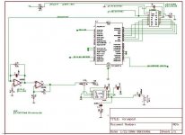
The idea is that a recorded at 5kHz, 8 bit, mono wav file is stored in an eeprom as a hex file, then goes thru a DAC (signal comes out as current for this particular chip) to a current2voltage converter (LM358 op-Amp) with a high pass filter that passes everything above 20Hz, then another gain stage (LM358), then an Audio op-Ap (LM356). The software is programmed into a PIC chip.
I attached the schematic.
The trouble is that the circuit/software works, but sound quality is very poor. You can hear the recorded file, and while you can understand what it says, and it does not seem to be terribly distorted, it is corrupted with lots of noise.
This is for a school project and I have no choice about the memory chip and process (altho I am open to suggestions). What I really need help with is filtering and noise control. I don't have to use those op-Amps.
Another question: is it better to use BJTs than op-Amps for sound?
Thank you!
Sophi
Attachments
LM358 can be exchanged for other OP-Amp.
For this project maybe a TL072 would be a good choice.
But, I am not convinced OP-Amp LM358 is responsable
for the poor sound quality in this circuit.
Only 8 bits at 5 kHz is not top of digital storage of sound.
Maybe you can make a better filter in first OP-Amp.
There are members here that have threads about such Digital to Analog Conversion circuits (DAC)
and I/V-filters they have built and developed.
Maybe you should have a look and ask in Digital forum
Nora,
If you sampling rate is 5 kHz... then your low pass filter after the DAC should be set at a maximum frequency of 2.5 kHz. This is called the Nyquist therem or something like that. Your filter should also be "multiple order", at least 2nd order (8th order would better), to really kill the hash in the higher frequencies...
I see you have 2 op amps there... your filters could be incorporated "around" thos amps very easily.
Google on"2nd order lowpass op-amp" and you find lots of circuits... you want a "Butterworth" for simplicity You can turn each amp into a 2nd order to achieve a 4th order. This will give you a vast improvement.
Set your "cutoff" frequency between 2 and 2.5 kHz and punch through the equations.
If you can't find a circuit, lemme know...
Hi,
the virtual earth (inverting) opamp has no gain setting resistor in the input line. Is this normal for a I2V convertor?
Where is the 20Hz high pass filter?
Are you the pupil or the teacher?
Full marks for resourcefullness but zero marks for independant research and/or problem solving.
the virtual earth (inverting) opamp has no gain setting resistor in the input line. Is this normal for a I2V convertor?
Where is the 20Hz high pass filter?
Are you the pupil or the teacher?
Full marks for resourcefullness but zero marks for independant research and/or problem solving.
Hi-
Thanks for all the replies.
Um..what I already have will work for a grade....I want to make it better!
Would I want a low pass or a band pass filter (I am going to look at Butterworth).
Is this right- sampling frequency (mine- 5kHz) is 2x bandwidth and bandwidth is the frequency at which I can get sound (needs to be minimum of 3kHz for clarity).
So I should design my filter around 3kHz and record at sampling rate of 6kHz? BTW 6kHz is the fastest I can have with my Micro Processor speed.
Sophi
Andrew-
I am the pupil.
The op-Amp directly after the DAC is set up as a current2voltage converter....it takes a negative (backwards) current at pin 2 input and converts it to a positive voltage pin 1 output. So no need for a resistor.
The other part of the op-Amp is a non-inverting op-Amp.
Hope that clears things up for you-
Sophi
The filter attached to the first op-amp (4.7 k || 470pF) is actually a low-pass filter, not an high-pass one as you have mentioned. The basic math (f=1/(2*pi*r*c)) shows that the cutoff frequency of that filter is set whay too high (almost 70Khz), and this is your main problem.
I would use a sharp filter of at least 4th order, manually tuned to provide at the same time minimum attenuation at 2.5Khz and maximum attenuation at 5Khz and above. Note that this noise that you hear through the loudspeaker is nothing but aliasing components from 5Khz upwards, in fact, everything coming out from the DAC at 5Khz and up is just trash and should be discarded.
If you have some unused processing power in your PIC, you may consider operating the DAC at 20Khz and fillng the three new samples created between each 5Khz sample with linearly interpolated values. You may consider second order interpolation, altough I think that it would be prohibitive in processing power terms. But, why interpolating at 20Khz? Because it will reduce dramatically the amount of 'trash' coming out of the DAC between 5Khz and 20Khz (it will be actually placed at 20Khz and above), making filtering much easier. (By the way, this technique is called 'oversampling', by a 4x factor).
Yes Sophi,
If you need 3 kHz on the upper end you need to sample at twice that frequency (absolute minimum... Nyquist rule).
Then follow your DAC with as much low pass filtering as you can create @ 3 kHz
Hint: the cap in first op amp can be adjusted to a better value...
Hint: the second op-amp can be used a filter stage more effectively if you convert to an inverting design...
If you are planning to play voice through that circuit, I recommend slightly increasing the samplng frequency, up to 6 or 7.5Khz, even at the expense of reducing the resolution to 6 bits per sample in order to conserve EPROM space. It would sound much like a conventional telephone this way. Note that 4x oversampling will introduce two extra lower bits of precision, so what you would have to do in your code is just to load the 6 bits of sample data in the higher 6 bits of an 8 bit register and pad the two lower bits with zero (then, the interpolation process will put useful stuff in those two bits).
Edit:
I've been checking the datasheet of the LM386. Do you really need a gain of 200 as it has been set by placing a 10uF capacitor between the gain pins? Note that this chip powered from +5V and driving an 8 ohm load is only capable of 3V peak to peak output (1.5V amplitude, approx 200mW, ie: not loud at all), that would be reached with just 7.5 milivolts of input amplitude with the volume setting at maximum. That makes me wonder what current amplitude values are being employed by the DAC.
A 9V or 12V supply would be more adequate. Also, a bypass capacitor of only 100nF is not likely to cause any PSRR improvement, according to the datasheet 10uF is a good value for it.

Thanks everyone-
Poobah and Eva- 470pF is a typo, should be 700pF but no matter I am still off by a factor of 10!
Eva- thanks so much for taking the time to look at the data sheets. I have no experience designing/building multiple poled circuits but you have given me some great advice to start researching.
I am using +9V for the LM386 already- I will try 12V.
On page 3 of the data sheet, the very last sentence says use a 0.1uF cap or a short for bypass. I must be misunderstanding the data sheet or reading from the wrong place?
The DAC uses nearly its max. -0.5mA.
So far as the gain goes, yes it was pretty soft with the 250uF shown in the data sheet, but with 1000uF its nice and loud.
Andrew- now look what you did!
Sophi
Poobah and Eva- 470pF is a typo, should be 700pF but no matter I am still off by a factor of 10!
Eva- thanks so much for taking the time to look at the data sheets. I have no experience designing/building multiple poled circuits but you have given me some great advice to start researching.
I am using +9V for the LM386 already- I will try 12V.
On page 3 of the data sheet, the very last sentence says use a 0.1uF cap or a short for bypass. I must be misunderstanding the data sheet or reading from the wrong place?
The DAC uses nearly its max. -0.5mA.
So far as the gain goes, yes it was pretty soft with the 250uF shown in the data sheet, but with 1000uF its nice and loud.
Andrew-
now look what you did!Sophi
poobah said:Nora,
If you sampling rate is 5 kHz... then your low pass filter after the DAC should be set at a maximum frequency of 2.5 kHz. This is called the Nyquist therem or something like that. Your filter should also be "multiple order", at least 2nd order (8th order would better), to really kill the hash in the higher frequencies...
I see you have 2 op amps there... your filters could be incorporated "around" thos amps very easily.
Google on"2nd order lowpass op-amp" and you find lots of circuits... you want a "Butterworth" for simplicity You can turn each amp into a 2nd order to achieve a 4th order. This will give you a vast improvement.
Set your "cutoff" frequency between 2.000 and 2.500 Hz and punch through the equations.
If you can't find a circuit, lemme know...
Eva said:The filter attached to the first op-amp (4.7 k || 470pF) is actually a low-pass filter, not an high-pass one as you have mentioned. The basic math (f=1/(2*pi*r*c)) shows that the cutoff frequency of that filter is set whay too high (almost 70Khz), and this is your main problem.
Yes, 70.000 Hz filter is just too very high.
To get a 2.500 Hz filter, you should change cap 470pF, which is parallel across 4.7 k resistor.
4.700 Ohm and 10 nF capacitor will give filter at 3380 Hz
4.700 Ohm and 15 nF capacitor will give filter at 2257 Hz
If you change resistor, too
4.7k in series with 1.5k and a cap 10 nF across these both resistors
will give 2567 Hz
Try this first ( or 4.700 with 10 nF ) and tell if there is a better sound.
Nora:
Read that last paragraph of the datasheet more carefully, indeed they talk about bypassing, but not about the "bypass" pin of the IC, they talk about bypassing the inverting input to ground for high-gain configurations (and you don't need that because yours is connected directly to ground).
You don't even need a big gain because the DAC is producing 500uA, that get converted to 2.35 volts in the 4700 ohm resistor, and further amplified to 5.9V !!! in the second gain stage. Even removing the 10uF capacitor shown in your schematic between GAIN pins (1 and 8), the IC would show a gain of 20, so it will get overdriven even with the 100K pot adjusted for minimum volume.
You should recalculate the V/I converter to produce a more reasonable output voltage (500mV or so) and remove the additional gain stage. You should also check the signal coming out of the DAC, since it may be receiving the wrong digital data and producing a very weak output, particularly if you don't experience serious overdrive issues on the LM386 with the current gain configurations (it should sound loud and very distorted even with the volume adjusted at minimum).
Also, the first LM358 op-amp will have trouble to produce 2.35V with its 5V single supply configuration (except if it has also -5V), but the second one won't be capable of handling 5.9V at all. You sould be careful with DC biasing and signal levels when employing such low supply voltages (LM358 output can swing near ground or -Vee, but it will clip 2V below +Vcc, same applies for its inputs...)
Concerning the PSU of the IC, 9V should be already adequate, if you rise it to 12V check for overheating.
Hi Eva-
The signal from DAC seems to be correct- that is, I can hear the sound file through the speaker and it is distinctly the words that I recorded.
Yes, serious overdrive-distortion with LM386 at highest volume. I have 100k on the pot in the schematic but I never measured it, it could be much less.
My plan is:
1) Re-record sound file at 6kHz
2) Re-calculate first stage filter for 3kHz LM358 !!
3) Change I2V for a higher voltage output LM358
4) Replace ground of LM358 with -5V
5) Remove 2nd gain stage (for now) LM358
6) Rewire all for clean lines
7) Start with gain of 20 in LM356
I won't be doing this until the end of next week.
Thanks again-
Sophi
The output voltage of the I2V is only 20mV but changing the 4.7 resistor has previously resulted in no change in output voltage. I will rewire and check again. The data sheet for the DAC shows an I2V with a 5k.You should recalculate the V/I converter to produce a more reasonable output voltage (500mV or so) and remove the additional gain stage.
The signal from DAC seems to be correct- that is, I can hear the sound file through the speaker and it is distinctly the words that I recorded.
Yes, serious overdrive-distortion with LM386 at highest volume. I have 100k on the pot in the schematic but I never measured it, it could be much less.
My plan is:
1) Re-record sound file at 6kHz
2) Re-calculate first stage filter for 3kHz LM358 !!
3) Change I2V for a higher voltage output LM358
4) Replace ground of LM358 with -5V
5) Remove 2nd gain stage (for now) LM358
6) Rewire all for clean lines
7) Start with gain of 20 in LM356
I won't be doing this until the end of next week.
Thanks again-
Sophi
- Status
- This old topic is closed. If you want to reopen this topic, contact a moderator using the "Report Post" button.
- Home
- Amplifiers
- Solid State
- Please help with sound quality- op-Amps