Upgrades
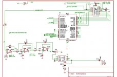
I've attached a new schematic.
Mods: I recorded my speech file as 8 bit mono at 6000Hz. After the I2V circuit I'm using an LM358 to make a 4th order- I think (I never made one before so if its wrong, please be gentle with me") - LP filter for 3700Hz. I assume correct wiring since all wires have been checked and rechecked.
- LP filter for 3700Hz. I assume correct wiring since all wires have been checked and rechecked.
To complicate things, my local radio station seems to be tuned to my circuit. AARGH! Nothing worse than trying to hear MY file and getting some deoderant advertisement.
While the sound quality is much(!) better, it is still very noisy and when I turn the volume pot, the sound is really distorted and humming. At near to highest volume, the sound is not loud enough. At highest volume, it likes to blow my ears out but is totally distorted.
1. Do I need to make my LP filter for 3000Hz- will that really make a big difference?
2. I'm using DAC0808, should I be using a DAC that's "meant" for audio?
3. Should I have a more-poled high pass filter on the end?
4. Any other ideas?
Thanks very much-
Sophi
I've attached a new schematic.
Mods: I recorded my speech file as 8 bit mono at 6000Hz. After the I2V circuit I'm using an LM358 to make a 4th order- I think (I never made one before so if its wrong, please be gentle with me
- LP filter for 3700Hz. I assume correct wiring since all wires have been checked and rechecked. To complicate things, my local radio station seems to be tuned to my circuit. AARGH! Nothing worse than trying to hear MY file and getting some deoderant advertisement.
While the sound quality is much(!) better, it is still very noisy and when I turn the volume pot, the sound is really distorted and humming. At near to highest volume, the sound is not loud enough. At highest volume, it likes to blow my ears out but is totally distorted.
1. Do I need to make my LP filter for 3000Hz- will that really make a big difference?
2. I'm using DAC0808, should I be using a DAC that's "meant" for audio?
3. Should I have a more-poled high pass filter on the end?
4. Any other ideas?
Thanks very much-
Sophi
Attachments
OK fine, yes I did learn that fundamental law.
Applied it by re-recording at 8kHz. Much less noise. A much better proof than all that math!
But still not very loud. In fact, I have to hold my ear to the speaker to hear anything. Grrrr.
*edit- I removed the 1000uF cap next to the speaker so now it is 470uF. Everything is loud and clear. Yes some noise but acceptable (!YAY!) although I'd still be happy to take suggestions on how to make it better! The wierd thing is that there is only one spot when I turn the pot that things work....
Sophi
If you can hear some radio station, it's because some audio stage is unstable and oscillating, thus acting as a AM/FM receiver. This has a lot to do with layout, particularly with unwanted capacitances between IC pins (in case of breadboarding) and with large wires in feedback loops. The LM386 is probably the most prone to oscillation IC in your circuit, since the op-amps are slow and connected as followers, and you have mentioned that doing stupid changes like swapping 1000uF and 470uF output capacitors or turning a bit the gain potentiometer improves sound. Note that everything is very sensitive to layout and responds in unexpected ways when oscillation is present.
Have you tried my oversampling approach with linear interpolation? This works wonders, allowing for higher perceived quality with a lower sample rate. For example, if the current sample is 47 and the next sample is 90, for 4x oversampling you would have to output the samples 4 times faster and insert the following samples between 47 and 90:
90-47 = 43
43/4 = 10.75 (you will have to use 11 bits for these variables)
output 47
output 47+10.75=57.75 (round to 58)
output 57.75+10.75=68.5 (round to 69)
output 68.5+10.75=79.25 (round to 79)
output 90 (this is where the next cycle begins)
It's very important to output the samples at a constant rate, so you have to trace your code by mind, calculate how much microseconds everything takes to execute, and add the exact number of NOPs and repetitions of delay loops. Remember that jumps take 2 clocks when they are taken and skipped opcodes still take 1 clock (at least on the PIC12C family, the one I'm more acquainted to).
Also, you should add a pull-down resistor to the outputs of the LM358, 1K would suffice. The datasheet hardly discusses that topic, but in my experience (that is, looking at everything with an oscilloscope) its small-signal HF behaviour improves a lot with that resistor.
-If I recall, the DAC0808 is a current output DAC. You should remove the 5.6K resistor from the DAC to the I-V converter, as having an R there would delinearize the output of the DAC.
-You can also take advantage of the I-V converter stage being an op-amp and add an integrating capacitor there (parallel with the 4.7K FB resistor, so you effectively get a 5th-order LPF.
-Does the output amplifier stage need to have an AC-coupling capacitor at its input? Check ap-note...
- Are you working the op-amps on a single supply voltage? If so, please check that the op-amps are biased properly...
You may want to consider changing the op-amp to something less prone to oscillation, as Eva pointed out, picking up an AM station usually means the thing is oscillating... An LM324 is a very tame quad op-amp you could try...
Cheers!!
Clem
HI-
Thanks very much for responses.
Eva- I don't know what "oversampling approach with linear interpolation" is, although I remember you mentioned it a couple of weeks back. I'll Google it but it may be too advanced for me. Also, my code is in C and I use a built-in compiler I2C function to get my data into the PIC. I doubt I would get the I2C timing right in Assembly
I'm going to put the 1k pull-down resistors in though and thanks for the explanation of why my radio station is playing! Getting rid of that will be a relief!
Clem- oops 5.6k is a typo, sorry. As for biasing the LM358's, I tested them with both -9 and gnd at pin 4. Leaving it single supply (pin4 to gnd) seemed to sound better. Is that what you meant by single supply?
Good idea to make this 5th order.
Yes, Ap-note pg. 16 shows an example circuit with cap on input.
Re: LM386 -I was advised to use it as it is "used for sound" and
"fast". I do have LM324's here.
Sophi
You will never get perfect sample synchronization with PIC code writteh in C, and calling unknown third-party functions only makes it worse and more unpredictable. I suppose you are now using a timer to calculate variable delays in order to keep the thing synchronized, as this is the best approach allowed in C.
In my previous post I have explained what you have to do in order to get oversampling and interpolation. It's intuitive. All you have to do is to output samples at 4 times the original frequency and fill the 3 new samples created between each pair of original ones with interpolated data (the process shown in my previous post).
Concerning the LM324 and LM358, these are the same op-amp model, but LM358 is the dual version and LM324 is the quad, so there is no point to exchange them other than size reduction and convenience. This device is not likely to oscillate.
This is some pseudo-code to implement 4x oversampling with linear interpolation (8Khz input sample clock, 32Khz output sample lock):
retrieve_current_sample
reset_timer
time=timer_value
do {
retrieve_next_sample
step=(next_sample-current_sample)>>2 (fast divide by 4)
k=4; do {
time+=31.25us (this is the more precise approach to clock it)
while (timer_value<time) {}
output_current_sample
curret_sample+=step
} while (--k!=0)
current_sample=next_sample
} while (some_sound_stop_condition)
This code does not take care about the fixed point math required to deal with decimal numbers in a PIC, but this is another story. You have to understand interpolation and oversampling first.
Also, the (timer_value<time) comparison is tricky due to both timer register and time variable wrapping, but it may be made to work if time and timer_value take more than 31.25us*2 between each wrapping.
Sophi - perhaps your C compiler has the math (fp) routines built-in anyway. If it does, Eva's code will work straight off.
OTOH, it may be worth a try to just output at a higher rate without the need for interpolating in-between. i.e. just copy the current value and output it 4 times at a 4X rate - so much for zero-order hold... Definitely no way as good as linear interpolation but still having an advantage than running at the lower speed (but I don't quite remember my DSP stuff - will the in-band aliasing components due to that just destroy any advantage?).
Or, forget the linear interpolation and put it into an FIR, making the interpolated samples more "correct" - this one I'm pretty sure will work!!.
"Concerning the LM324 and LM358, these are the same op-amp model, but LM358 is the dual version and LM324 is the quad, so there is no point to exchange them other than size reduction and convenience" --oops, thanks for the correction. Didn't realize that, always had the impression the 358 was a different circuit....
Cheers!!
In the telephony network, they use 8000 Hz sampling
frequency @ 8 Bit, which gives 64 Kbps per Channel.
Frequency range is around 300 Hz .. 3400 Hz.
Linear Coding would only give
SNR(RMS) (dB)=6.02×n+1.76 dB = 20 db Signal to Noise,
which is unacceptable low. T overcome this,
companding according to A-Law in Europe
or mu-Law in America is used.
A-Law / my-Law samples 12 Bits, compresses down to 8 Bit using a non-linear transfer function (this function is described
by A-Law / mu-Law). On the receiver, the signal is again expanded. Digital companding works quite well as there
are no level problems (loss, frequency linearity) as in analog
transmission. The basic idea is, to use more bits of resoluition
for the lower volume signal components, where the human
ear is more sensitive, at the price of lower resolution at
higher volumes. It spreads the S/N-Ratio more evenly
over the amplidude range. In linear coding, S/N
falls with lower amplidudes. For voice transmission
this is absolutely ok, everybody will confirm from own
expierience using the telephone....
Cooledit e.g. can produce mu-Law codes files. Decoding
in a PIC should not be too complicated using a table-driven approach, though I don't have an algorithm for that.
Regards,
Stephan
- Status
- This old topic is closed. If you want to reopen this topic, contact a moderator using the "Report Post" button.
- Home
- Amplifiers
- Solid State
- Please help with sound quality- op-Amps