Hi
Recently I found an old article of a power amplifier.
It uses the technic of "composite collector load class A", means the output transistor will always stays at Class A using such a technics......
It seems had been post on the "Practical Electronics" magazine, UK.....
Please help me out about the operation of this ckt.
cheers
Coffin
Attachments
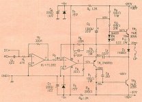
I think this circuit has a lot in common with the (in)famous Quad current dumping principle.
The bottom output device is actually driving the top output device and thus it never stops conducting. However, the zero current crossing glitch as seen by the input stage may be actually worse in these circuits than in a properly biased conventional class B or AB one.
The bottom output device is actually driving the top output device and thus it never stops conducting. However, the zero current crossing glitch as seen by the input stage may be actually worse in these circuits than in a properly biased conventional class B or AB one.
")
Hi
Recently I found an old article of a power amplifier.
It uses the technic of "composite collector load class A", means the output transistor will always stays at Class A using such a technics......
It seems had been post on the "Practical Electronics" magazine, UK.....
Please help me out about the operation of this ckt.
cheers
Coffin
I have investigate the output buffer stage of this circuit and and I note an interest behavour. Especially the distortion character is of interest. It is nearly constant and don't enhance to higher frequencies. This is because the use of the capacitors C3 and C4. I think, there are for lead-lag compensation.
I have changed some resistors to higher idle current as at the original circuit. Additional I use some bjt medium power devices in parallel.
My test exemplare of this buffer amplifier topology sounded very fine; especially by midrange and high frequency aera. The disadvantage is follow: I cannot use load impedance below 16 ohms, because the distortion goes to extremly high values. Therefore I would it only use for vintage full range and midgange/tweeter speaker devices, that have high efficiency and 16 ohms impedance (diatone, supravox, auratone, PHL, glockenklang, fostex, saba and similar).
"BUF Olson BjT.pdf"
Parameter: in/out: 10Vss, R-load: 16 ohms, 100KHz sine wave, voltage gain: <1
1) Damping factor
2) Frequency Response
3) 100 KHz Fourier Analysis lin (K2: 17,5mV K3: 0,4mV)
4) 100 KHz Fourier Analysis log
5) 1MHz
6) Circuit
7) 1MHz without C3
8) Frequency Response without C3
Attachments
Hi
NO one heard this?
Looks similar to a driver stage of my my Swinnik amp I did in mid-70'th.
Member
Joined 2009
Paid Member
I think this circuit has a lot in common with the (in)famous Quad current dumping principle.
The bottom output device is actually driving the top output device and thus it never stops conducting. However, the zero current crossing glitch as seen by the input stage may be actually worse in these circuits than in a properly biased conventional class B or AB one.
It looks a lot like D. Self Class XD....
- Status
- This old topic is closed. If you want to reopen this topic, contact a moderator using the "Report Post" button.
- Home
- Amplifiers
- Solid State
- has anyone heard of this? composite collector load.....