Your cct above will need some "strong" input signal to drive, because it drive emitors.
Frederico's input signal is driving base, ordinary preamp should drive Frederico's easily
Well hopefully we all have extraordinary preamps

And anyway as it has been pointed out this is actually an easy circuit to drive. I have played with the idea of current input stages, another time...
B Cullingford said:When I was playing around diamond buffers I found
that putting small value resistors into the emitter of the input transistor made the linearity worse,
I am afraid, when building a non-global-feedback amp,
and get a good linearity,
we have to use high current gain and rather high values for those resistors that set the voltage gain in each stage.
This means a 'no-feedback amp' will have plenty of local feedback, collector and emitter,
to get good linearity and low distortion.
Hi lumanauw
Actually many times the 'off topic' comments are the most thought provoking, almost any comment that comes with a circuit attached is at least worth a look. It took longer to write the responce than to read and analyse, it was downloading while I read something else, so thanks for contributing!
Bill
lineup
Maybe I did not explain my small resistors well enough and a picture would have helped, but it is late and I don't have the energy to fire up the other computer and draw some circuits to explain right now, except that no resistor was far better than a resistor for linearity (this was real life not sims).
Bill
B Cullingford said:
Well along time ago, memory is a little fuzzy, I need to find my notes or look at the input/VAS stage I built but never quite finished (no PCB, dead bug style but no ICs) but I did not do serious listening, at the time I was just experimenting with trying to find very linear nofeedback stages just to see how possible it was. Using transistors as diode is, I believe, a common arrangement for the input of CFP op amps since it solves the offset problem, it is possible to use some open loop and they can sound good, though again my personal listening was limited and along time ago.
As soon as I get my electronics bench set up so I can find things...
Oh and I've got to stop designing and just make something!
Bill
Hi Bill,
thanks for your input!
Yes, I guess it's time to leave the armchair design stage in favour for some real circuits for me too this year, stay in touch regarding that circuit!
Cheers Michael
Thank you all,
in particular, I wish to thank you, Bill
for the time spent and the valuable comments.
I apply many of your suggestions and the circuit
is now better than before both regarding stability and THD performance.
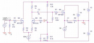
now we find about 2mA and there is room.
I decrease the gain to 34 in such a way to have full power
for 1Vrms at the input.
At first I put a 25k res on the collector of Q1 since I do not really need
55Volts in that point.
Then I added a lowpass (5k plus 100uF) on the supply to filter out noise.
I try to insert noise at each device leg. q2 and q3 are the most prone to noise
(expecially common mode) but they cancel each other.
Finally I add a small (30pF) cap on the emitter of Q3 which, along with
the 50pF cap on the base of Q4, decreases the VHF noise sensitivity.
All the component values have been changed so we find current of the order:
Q1 (1mA) Q2(2mA) Q3(12mA) Q4(12mA) Q5(40mA) Q6 (200mA)
Q5 and its complementary have been changed to MJE15034/35 , better HF THD components.
Thermal stability:
Q1 and Q2 rougly compensate
D1 has been added to compensate Q3
D2 has been added to compensate Q4
D3 works with Q6 ( the four output device)
Q5 is not compesated and I ask you all some hint.
Yes, I could change the Q4-Q5 in a CFP but
It is a local NFB element and I prefer to avoid this.
Yes, I tried this and it works well. They act as diode and they balance well and the balance
is temperature independent too.
but input resistance decrease from 200k down to 20k and, though not very low, I prefer to avoid.
Yes, I could put a CCS but they have NFB.
With this set up I have a THD% of 0.4% at 300W/4 Ohm.
(simulation)
some open questions:
- emitter output res, now 0.1 Ohm.
- Q5 stability
- Open Pot question (gain pot)
- stabilized supply
other?
I continue working
bye
Federico
in particular, I wish to thank you, Bill
for the time spent and the valuable comments.
I apply many of your suggestions and the circuit
is now better than before both regarding stability and THD performance.
...your second stage is only running at about 0.7mA not enough cuurennt to drive ...
now we find about 2mA and there is room.
times 20, times 10K is about 100 or 40dB. Do you really
need this much? A typical amp (is there is such a beast)
has a gain of about x20 or 26dB.
I decrease the gain to 34 in such a way to have full power
for 1Vrms at the input.
the 35K resistor is a wonderful path for PS noise into the circuit,
At first I put a 25k res on the collector of Q1 since I do not really need
55Volts in that point.
Then I added a lowpass (5k plus 100uF) on the supply to filter out noise.
I try to insert noise at each device leg. q2 and q3 are the most prone to noise
(expecially common mode) but they cancel each other.
Finally I add a small (30pF) cap on the emitter of Q3 which, along with
the 50pF cap on the base of Q4, decreases the VHF noise sensitivity.
So my suggestion:
1/increase Q1 emitter...
All the component values have been changed so we find current of the order:
Q1 (1mA) Q2(2mA) Q3(12mA) Q4(12mA) Q5(40mA) Q6 (200mA)
Q5 and its complementary have been changed to MJE15034/35 , better HF THD components.
Thermal stability:
Q1 and Q2 rougly compensate
D1 has been added to compensate Q3
D2 has been added to compensate Q4
D3 works with Q6 ( the four output device)
Q5 is not compesated and I ask you all some hint.
Yes, I could change the Q4-Q5 in a CFP but
It is a local NFB element and I prefer to avoid this.
The other thing I did is swap the input transistors,
the advantage is that if you match NPN1 and NPN2 (and the PNPs 1 & 2)
you get no offset (well maybe a little)...
Yes, I tried this and it works well. They act as diode and they balance well and the balance
is temperature independent too.
but input resistance decrease from 200k down to 20k and, though not very low, I prefer to avoid.
Yes, I could put a CCS but they have NFB.
With this set up I have a THD% of 0.4% at 300W/4 Ohm.
(simulation)
some open questions:
- emitter output res, now 0.1 Ohm.
- Q5 stability
- Open Pot question (gain pot)
- stabilized supply
other?
I continue working
bye
Federico
Attachments
As I've posted to a couple other threads recently: There is a thread that discusses emitter resistors elsewhere on this site where John Curl mentions that for a class ab amp that there should be 15 - 25 mV across the emitter resistors (for best linearity) - check the thread out for details and references (sorry no link), your 200mA and 0.1 ohms falls into the middle of this. Fine adjustments around this value may result in lower distortion (or higher!) and it may depend on load, and maybe we should just worry about this when we actually build it.
Someone else mentioned in another thread recently that they liked to have about 0.6 to 0.7 volts dropped across the emitter resistors at the max load current so that load limitting transistors could easily be used, it is possible to do both things but I think is likely to lead to a larger value emitter resistor which leads to more distortion, not too much a problem with a feeback design. Current limiting is important for a commercial design (or 'over' building) but it is said you can get better sound without the current limiting.
I had fellow tech remove the curent limiting transistors on his own - said it sounded better, then it blew up. That said my next design will probably not have current limit t's.
Bill
Hi, Federico,
I like your design
If I may, I wanted to propose to change 4k7 and 1k3 (at pre-pre driver and pre-driver) to be changed to Bootstrapped. Divide those R to half values in series, and put bootstrapp capacitor between this juction and output node.
The reason is like this : when the output signal is full positive or negative, one side of this 4k7 and 1k3 will experience near 0V in them, while in the opposite half, others will experience near 110V (with +/-55V rail). With bootstapped each half will experience about the same voltage drop, in nearly all audio signal.
Have you tried CFP for output stage? Like NP uses in Threshold series? These output stage is very powerfull, it is self correcting to G=1, suitable for no-feedback amp.
Hi, all.
I like people who try to do samething different. They are looking
for breakthrough, for better sound.
Power Operation Amplifier topology make samething bad for
sound quality and listenig to class D amp not make me happy.
Better situation is in Valve territory, but not so in SS.
May be one of the way to better sound is NOF amp.
But this is not inough to build Power OP and just drop the overall feedback.
Federico, i built low distortion amp very similar to you 2-3 years ago and result from sonical point was good, but not good inough.
Since then my amplifiers have one simple VAS and one power stage(capacitor or transformer coupled), very good parts and sounding much better.
That is only my own experience. You do not have to accept that
and continue your project.
Hi rozak,
probably due to my poor knowledge of english language,
I completely miss the meaning of your post.
in particular:
where is the difference between your old style and the actual one?
No feedback vs. feedback?
What do you mean with "one simple VAS and one power stage"?
no drivers? no input stage? sinple MOS output?
are you saying that the key is in simple and short circuits with good components and some NFB?
I do not think so. I read and write ideas on this and other fora
to learn something and, obviousy, my wish is to succeed to
design a better amplifier. It is not a question of accept or
not your ideas. If your (or other ) ideas are well explained and result to be founded and convincing, I'll try to adopt them or
part of them in my designs.
The only thing I will not do is to follow ideas not supported by
reasoning. The "because it sounds better" story is not enough
to try a topology since " to try" means a lot of work.
bye
Federico
probably due to my poor knowledge of english language,
I completely miss the meaning of your post.
in particular:
Federico, i built low distortion amp very similar to you 2-3 years ago and result from sonical point was good, but not good inough.
Since then my amplifiers have one simple VAS and one power stage(capacitor or transformer coupled), very good parts and sounding much better.
where is the difference between your old style and the actual one?
No feedback vs. feedback?
What do you mean with "one simple VAS and one power stage"?
no drivers? no input stage? sinple MOS output?
are you saying that the key is in simple and short circuits with good components and some NFB?
That is only my own experience. You do not have to accept that and continue your project.
I do not think so. I read and write ideas on this and other fora
to learn something and, obviousy, my wish is to succeed to
design a better amplifier. It is not a question of accept or
not your ideas. If your (or other ) ideas are well explained and result to be founded and convincing, I'll try to adopt them or
part of them in my designs.
The only thing I will not do is to follow ideas not supported by
reasoning. The "because it sounds better" story is not enough
to try a topology since " to try" means a lot of work.
bye
Federico
Hi Federico,
---------------------------------------------------
probably due to my poor knowledge of english language,
I completely miss the meaning of your post.
---------------------------------------------------
Sorry, my english is very poor. It take me hours for reply.
------------------------------------------------------
It is not a question of accept or
not your ideas. If your (or other ) ideas are well explained and result to be founded and convincing, I'll try to adopt them or
part of them in my designs.
The only thing I will not do is to follow ideas not supported by
reasoning. The "because it sounds better" story is not enough
to try a topology since " to try" means a lot of work.
-------------------------------------------------------
You are absolutly right. I can't prove you anything. I just tell
you a story.
---------------------------------------------------------
What do you mean with "one simple VAS and one power stage"?
no drivers? no input stage? sinple MOS output?
---------------------------------------------------------
---------------------------------------------------
probably due to my poor knowledge of english language,
I completely miss the meaning of your post.
---------------------------------------------------
Sorry, my english is very poor. It take me hours for reply.
------------------------------------------------------
It is not a question of accept or
not your ideas. If your (or other ) ideas are well explained and result to be founded and convincing, I'll try to adopt them or
part of them in my designs.
The only thing I will not do is to follow ideas not supported by
reasoning. The "because it sounds better" story is not enough
to try a topology since " to try" means a lot of work.
-------------------------------------------------------
You are absolutly right. I can't prove you anything. I just tell
you a story.
---------------------------------------------------------
What do you mean with "one simple VAS and one power stage"?
no drivers? no input stage? sinple MOS output?
---------------------------------------------------------
Attachments
If I may, I wanted to propose to change 4k7 and 1k3 (at pre-pre driver and pre-driver) to be changed to Bootstrapped. Divide those R to half values in series, and put bootstrapp capacitor between this juction and output node.
lumanauw,
I tried that configuration and it gave me e better distortion (THD)
but high order term tend to increase. In particular the switch off
distortion (crossover dist, I do not know) of the output stage go back to the driver and terms bejond 4a harm augment.
This is due to the fact( I think) that this is a NFB arrangment.
The effect (I repeat, the effect) of your suggestion is similar to those of connecting the emitter of driver and predriver each other with two res (and not to supply) and then connecting the mid point with the output. One can see a less variable current in
driverand predriver (they are less loaded), a decrease in THD
but an increse of the higher order terms.
bye
Federico
Hi, Federico,
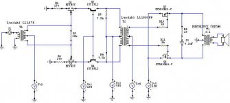
How about this one, connected to rail with CCS? No "feedback" from output node, but always constant current at any voltage swing.
Some commercial design like Densen do like you do, but I think it can be done better.
A good example is power amp design by Steven (No global feedback, but local feedback at output transistors).
If you want more simple, just put CFP for output stage, like NP's Threshold. They are self correcting towards G=1, very powerfull because the correcting force is in the form of currents (coming from collectors) and the first transistor's emitor is doing "sensing" more than giving current to the output speaker.
How about this one, connected to rail with CCS? No "feedback" from output node, but always constant current at any voltage swing.
Since you are not into heavy biased classA output stage (you are making only 200mA bias), for no-feedback power amp, I think you will need somekind of "local feedback" only around the output stage, to minimize this distortion, since nobody is "fixing" it, due to no global feedback available.In particular the switch off distortion (crossover dist, I do not know)
Some commercial design like Densen do like you do, but I think it can be done better.
A good example is power amp design by Steven (No global feedback, but local feedback at output transistors).
If you want more simple, just put CFP for output stage, like NP's Threshold. They are self correcting towards G=1, very powerfull because the correcting force is in the form of currents (coming from collectors) and the first transistor's emitor is doing "sensing" more than giving current to the output speaker.
Attachments
Thank you lumanauw,
I applied your suggestion and it works fine but not
better then before.
It perform very like (C) configuration (see attach).
I tried all those config. but they performed similar each other.
They are not equal, however, regarding supply load.
One can note twofold increase in current from A to D.
can you, please, give me a reference to this?
maybe a link?
I also tried CFP but always the same result: THD decreases but
high order terms increases.
(maybe, I donot implement it well)
bye
Federico
I applied your suggestion and it works fine but not
better then before.
It perform very like (C) configuration (see attach).
I tried all those config. but they performed similar each other.
They are not equal, however, regarding supply load.
One can note twofold increase in current from A to D.
A good example is power amp design by Steven (No global feedback, but local feedback at output transistors).
can you, please, give me a reference to this?
maybe a link?
I also tried CFP but always the same result: THD decreases but
high order terms increases.
(maybe, I donot implement it well)
bye
Federico
Attachments
Hi, Federico,
Steven's amp is in a thread "Is there anybody built a non feedback amp" by Lukio.
You got this from SIM or measurement? If you measure this via sound-card, there are noise in sound card.
I always take harmonic left-overs as water pillow analogy. If you press the low order ones, the high order ones will show up. If you don't press the low order ones, the high order ones will not show up.
Steven's amp is in a thread "Is there anybody built a non feedback amp" by Lukio.
THD decreases but high order terms increases.
You got this from SIM or measurement? If you measure this via sound-card, there are noise in sound card.
I always take harmonic left-overs as water pillow analogy. If you press the low order ones, the high order ones will show up. If you don't press the low order ones, the high order ones will not show up.
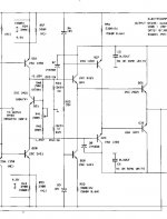
Steven's Amp
Steven's post
The circuit
Steven:
Together with a friend I designed and built in 1983 a class AB amplifier
that is overall feedback free and non-switching.
Below is the circuit of the amplifier and in the next post the servo that is used.
I removed the values and transistor types as I still have other plans with it.
It will give you an idea.
Steven's post
The circuit
- Status
- This old topic is closed. If you want to reopen this topic, contact a moderator using the "Report Post" button.
- Home
- Amplifiers
- Solid State
- another nofeedback amp