I've been working on a high voltage op-amp design at work in the last couple of days, to get someting to drive a 50pF load at about 40kHz up to +/- 80V. To do this I've used a standard three stage amplifier design, but leaving off the output buffer, as the 10mA I have throught the VAS stage appears to be more than enough to drive my intended load. What I would like to know is if there are any prblems in doing this, creating an op-amp without the traditional output stage buffer.
Any feedback would be greatly welcomed.
(I'll try and get a schematic up for the circuit tomorrow, in case people are interested)
Any feedback would be greatly welcomed.
(I'll try and get a schematic up for the circuit tomorrow, in case people are interested)
Yes,
if the load is not too heavy (low impedance)
and you have enough current in your VAS
you do not have to use output follower transistor(s).
May need to use two transistor VAS in darlington or like in the link below.
This 2 transistor 'buffer' will make sure the input stage does not get too heavy burdon, driving VAS.
Feedback used will correct the output voltage.
There are many examples of preamplifiers of OP-amp type
that is built like this.
Here is one Hi-fi Preamplifier in OP-amp style
using only Input and VAS stage:
http://www.mitedu.freeserve.co.uk/Circuits/Audio/gmpre.htm
If you see this post in this thread, you will find link to Douglas Self Amplifier Insitute.
In his Distortions article you can see some possibilities
how to setup VAS.
Help designing Input and Vas stage's
What about needed feedback and open-loop gain? The load will have a direct influence of the open-lopp gain, otherwise I see no other problems.
If you have low current requirements you could use a plain opamp with a floating power supply. Do you know what I mean? The output is manipulating with the power supply for the opamp, sort of cascode.
If you have low current requirements you could use a plain opamp with a floating power supply. Do you know what I mean? The output is manipulating with the power supply for the opamp, sort of cascode.
Hi, the output loar will be an approximate 50pA capacitive load running at most at 80kHz ((approx 40k to ground) with around 400 ohms of in line resistance before the load to help cut the amout of feedback recieved at the amp's output. This may further have a low pass filter (comming from the load side) added, as the output will be connected to the output side of a pulst transformer running a 10Mhz 80Vp-p signal, which I would rather not get back intot he amplifer circuitry.
The closed loop gain for the design will be a maximum of 10x, so there should be more than sufficient open loop gain (although I haven't done any calcs to prove this) to drive this up to the desired frequency)
The closed loop gain for the design will be a maximum of 10x, so there should be more than sufficient open loop gain (although I haven't done any calcs to prove this) to drive this up to the desired frequency)
bigparsnip said:Right, I've finly gotten round to getting the schematic for these into a format I can post up here, so if people would like to take a look, and let me know if you think it should work, that would be grand.
Andrew.
I think it will work very well.
You have good level of gain using two transistor VAS.
Output is Class A. Is it 10 mA?
With loads normal for preamplifiers, say higher than 5 kOhm,
you will get very low distortion.
Schematic shows gain=6, if I can see correctly.
What you do not show is supply voltage.
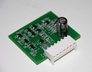
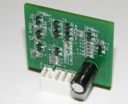
Hi, I got the boards back for these yesterday and have built a few up (not that I'l be putting them in an audio amplifier at the moment) for testing. However I did spot one rather silly mistake on my part in the design.
As Lineup states, the VASstage draws around 10mA under normal opperation, with a current limit at somwhere around 30mA. However, with the overall feedback network only being about 1k in the gain setting shown, the amplifier will go into current limiting before getting anywhere near the maximum output levels even with no load connected.
So, if people do come back to this in the future, be sure to increase the value of theses resistors to a suitable point if you want to drive anything more than a few volts on the output.
I'll see if I can't remember to stick some pictures of them up tomorrow.
PS, if anyone outhere who has a distortion or noise analiser is interested I may able to spare a couple to see how they "sound" when your running them
This is normally called a tranconductance amp. We have been using them in audio, at least 32 years, with the JC-2 line amp as an example. They can work very well, so long as the load is not too low in impedance. Be careful with slew-rate. Remember dV/dT= I(out)/C dV/dt is slew rate.


This, is a bit of slow repl, but here we go anyway.
These seem to work very well, I ended up playing around with some of the compoent values a bit as they got quite hot running at higher voltage levels (one went pop at +/-60V volts as I was a bit enthusiastic about the power handling of a couple of the sot-23's on the output). They seem to have about 75-80kHz of bandwidth, and will easily put through a very nice square wave with no overshoot or ringing with a suitable feed back limiting in place. I did hav a problem with one oscillating about 2.5Mhz when trying to lower the long tail pair bias current with a lower value compensation cap, but I guess I was just pushing my luck a little.
As for the other questions, yes it could have been a (lot) smaler, but I figred it was a quick job and the extra (yes, 1.6mm) PCB area wouldn't hurt in keeping the heat down.
But, I may be doing a second, faster version (trying for about 200MHz if anyone has any tips) which probably will end up with SOT-223 outputs, as it needs to kick out a fair bit more current (~100mA).
 _and_ trace thickness of 500 um
 peranders said:I have got a sample of a pcb laminate made of 0.1 mm + 2 mm copper
That sounds like copper sheeting with the protective covering still in place, are you sure you meant 2mm?
- Status
- This old topic is closed. If you want to reopen this topic, contact a moderator using the "Report Post" button.
- Home
- Amplifiers
- Solid State
- OP-AMP without an output stage?