Yes that pinout makes it so much easier. I in particular liked the previous Sanken versions, the SAP15 and 16 devices, as they even had a 0.22 ohms Re integrated. They stopped making those because apparently the SOA of the NiChr Re's was less than the transistors' SOA so the resistors blew before the active devices.
Anyway. One other purported disadvantage of the Sankens is that you can't directly access the output devices' base terminal, to put in a charge-suck-out resistor. I didn't find any practical disadvanteges from it; these are quite fast devices to begin with.
I had the privelege to discuss this particular point with D Self at the Amsterdam AES earlier this year, and he told me not to worry about that. Which I don't")
Jan Didden
Anyway. One other purported disadvantage of the Sankens is that you can't directly access the output devices' base terminal, to put in a charge-suck-out resistor. I didn't find any practical disadvanteges from it; these are quite fast devices to begin with.
I had the privelege to discuss this particular point with D Self at the Amsterdam AES earlier this year, and he told me not to worry about that. Which I don't
Jan Didden
>The 5 diodes are schottky's.
>The reason for that particular
>organisation is that the total
>string of diodes comes close
>to the correct bias for the Darlingtons.
OK. Thank You.
Do you mean that all 6 diodes
(both xsistorsworth)
in series are ~right for for the
total biasing?
Doesn't that imply both xsistors
are thermally as one?
So you couldn't have them on
separate heatsinks ....... ????
hitsware said:>The 5 diodes are schottky's.
>The reason for that particular
>organisation is that the total
>string of diodes comes close
>to the correct bias for the Darlingtons.
OK. Thank You.
Do you mean that all 6 diodes
(both xsistorsworth)
in series are ~right for for the
total biasing?
Doesn't that imply both xsistors
are thermally as one?
So you couldn't have them on
separate heatsinks ....... ????
Yes all diodes need to be in series. See app info attached.
I haven't thought about separate heatsinks, but it seem obvious that the two xsistors should be on a common heatsink for the same temp of all junctions and diodes.
Jan Didden
Attachments
Hi Jan,
If you can design with standard transistors, the On Semi parts pose zero problem. The Sanken parts lock you into very limited design options.
Just my thoughts on that matter.
-Chris
I can't understand the problem. On one hand, your design is fixed by the part. Even the operating points are fixed by the part. On the other hand, you have complete flexibility exactly the way you've done things for years. The big difference is that you now have access to something very close to the exact die temperature and you can use that sensor any way you want.In contrast, when you use the Onsemi ThermalTraks, YOU have to take care that the tempco tracking is set to the right value to avoid over- or undercompensation.
If you can design with standard transistors, the On Semi parts pose zero problem. The Sanken parts lock you into very limited design options.
Just my thoughts on that matter.
-Chris
anatech said:Hi Jan,
I can't understand the problem. On one hand, your design is fixed by the part. Even the operating points are fixed by the part. On the other hand, you have complete flexibility exactly the way you've done things for years. The big difference is that you now have access to something very close to the exact die temperature and you can use that sensor any way you want.
If you can design with standard transistors, the On Semi parts pose zero problem. The Sanken parts lock you into very limited design options.
Just my thoughts on that matter.
-Chris
Well, there isn't a problem really, I think. The discussion was about the tempco matching between the diodes and the xsistors. You are right that the Sankens are less flexible in how you want to configure your output stage, but you can also turn that into an advantage: integrated Darlingtons & bias diodes & pin-out to simplify pcb layout. I wasn't going to try to press anyone into a specific direction. I think
.It's just that if you decide to use integrated bias diodes, you might as well take the ones that have an almost zero tempco to begin with. But sure, using the OnSemi's you can also get there with a little bit more effort. Up to the designer.
Jan Didden
I've just been looking at the ThermalTrak devices, and I was very disappointed by the ON-semi application note. It keeps banging on about thermal runaway, which hasn't been a problem since we took up silicon. In ** years I have only ever seen one case of it, and that was in a remarkable design that used a thin metal panel as a "heatsink". The power transistors were mounted on black crackle paint! I should never have left it on over lunch...
Other worries; the majority of the THD tests were done with no load, which is so wrong it really makes you wonder what the author was thinking.
It is claimed (with no evidence) that no bias adjustment is required, which seems to imply that the integral diodes have some magical way of knowing about the Vbe's of the driver transistors.
Now I am prepared to believe that these are magnificent power devices, but the quality of this app note bothers me. What do other people think?
Indeed, neither OnSemi nor Sanken is very generous with application information, but the situation you paint is really dismal. It does reflect my earlier feeling that those ThermalTrak's were designed in great haste to jump on this particular bandwagon by plunking what appears to be run-of-the-mill 1N400x diodes on the transistor die.
I have *somewhat* better info from Sanken, which I only once found on the 'net and now seems to have disppeared. See attached.
Jan Didden
I have *somewhat* better info from Sanken, which I only once found on the 'net and now seems to have disppeared. See attached.
Jan Didden
Attachments
Hi Jan, how are things.
Thanks for the SAP app note. I can tell you that Sanken's doubts about the durability of the built-in emitter resistors were well justified. Cambridge Audio found that out the hard way. (not my designs, I hasten to add)
I really must try the ThermalTrak devices out some time. I would be very interested in seeing how fast the integral diode responds compared with a sensor on top of the transistor.
BTW, the ThermalTrak specs I have seen say nothing at all about the diode- no ratings, nothing. A bit worrying.
Hi
I know the roender amp using Onsemi thermal track.
I did found few of those transistors, but I still hesitate to use 3 in parallel, like in the roender amp, to get the right number of diodes for the correct bias. And anyway I don't have enough Onsemi thermal track transistors to do like in the roender amp.
Anyone try it using only one transistor per side with a VBE and only one thermal track diodes per side ?
My diy amp work super and it have a Self type II output and I would like to try the thermal track transistors on my amp.
Thank
Bye
Gaetan
DouglasSelf said:I really must try the ThermalTrak devices out some time. I would be very interested in seeing how fast the integral diode responds compared with a sensor on top of the transistor.
Certainly faster. On top, you have the diffusion velocity through the plastic and the mass of the sensor device.
Junction to backside for a typical die is 100 uSec to 1 millisecond. I don't think they are bonding a diode to the top of the chip, I think they patterned the diode into the basic device. Epoxy bonding to the top surface of the transistor die would be a temp and power cycle nightmare..ripping the aluminum off the die..
Laterally, I would expect the temperature settling time to be under a second or so..as a first guess. But boy, that datasheet has bupkus for data, eh?
They should at least provide an isolation voltage figure from diode to transistor. Is it made isolated tub out of nitride, reverse biased pn isolation..what?? It may go into crowbar conduction if the CE voltage reverses on transients.
Why not test the response? Put 10 milliamps in the diode forward bias, then apply a square wave dissipation to the transistor..watch the die Vf settle.
DouglasSelf said:BTW, the ThermalTrak specs I have seen say nothing at all about the diode- no ratings, nothing. A bit worrying.
Actually, it has Vr of 200 volts, and average rectified current as 1 ampere. It would have been nice had they categorized those numbers under the heading "integral diode parameters" We can't even tell if it runs 2.2 mV per degree C..
And I read somewhere that it's supposed to be a fast diode..
Horrible datasheet..
Cheers, John
do we need stable bias current with temp in the output stage? NO
do we need stable bias current with temp in the output stage? NO
This seams provocative but here is why (IMHO):
Self is writing in his book that an optimal Vq ( voltage drop on Re the ouput emitter resistor) would be 26mV for minimum distortion ( in Complementary EF stage).
This is empirically found but there is more to that if you understand why.
In a previous thread I wrote a memo explaining better the original paper ( difficult to read because typo errors) of Oliver ( from HP) on this subject.
He studied analytically the non linear output resistance of a class B amplifier. It is the non linear variation of this ouput resistance with output signal which is the cause of crossover distortion.
He showed that the distortion is minimum if: gmRe =1
where gm is the transconductance of the transistor at bias Io.
What does it mean?
gmRe=1 is equivalent to (Io/Vt)Re=1 where Vt is the thermal voltage kT/q
This is the same as Io Re=Vt or the voltage drop on Re = 26mV !
But this means that if the temperature increases, so does Vt and the current should follow proportionally if we want to stay in the minimal distortion condition !!!
So, the Vbias tracking circuit should have a different Tempco than the Vbe of the outpu transistor.
Lets evaluate this Tempco for Temp from T1=300°K to T2= 375°K. for Thermaltrak transistor
first the condition IoRe=Vt means that Io2/Io1 = T2/T1
Io1 = bias at T1 and Io2 is bias at T2. This is very important In our case Io2 = 1.25 Io1 and Vt ( at T2) = 26mv * 1,25 = 32.5
If the circuit is symetrical we may calculate the Tempco of Vbias for one half. The final Vbias Tempco is twice the result.
Vbias (at T1)= Vbe ( at T1) + Io1 Re
Vbias (at T2)= ( Vbe ( at T2) + Io2 Re + Delta Vbe )
(Delta Vbe) is the increase of Vbe at constant temperature T2 to take into account that Vbe operates at a higher current Io2.
Using the diode equation Io2/Io1 = exp ( Delta Vbe/Vt)
so (Delta Vbe) = Vt ln ( Io2/Io1 )
in our case Delta Vbe = 32.5 * ln ( 1.25)= 7.25 mV
Then
Vbias ( T1) = 0.6v + 26 mV = 0.626
Vbias ( T2) = 0.6V - (2mV * 75) +32.5 mV + 7.25 mV
= 0.450 V + 39.75 mV
And Tempco Vbias =( Vbias (T2) - Vbias(T1) )/ (T2-T1)
If we replace the values Tempco = -2mV/°C + (39.75 - 26)/75
Temco = 2mV/°c - 0.183 mV/°C = - 1.817 mV/°C
NOW the good point
If we look at the specs of the diode in the thermaltrak data sheet
At low current 1ma in the diode, Tempco is about 1.81mV/°C
So by using a Vbe multiplier like the Leach one and force 1mA in the diode leg, we can adjust for the right operating point at room temperature and have the two diodes tracking optimally !!!
So Thermaltraks OK ??
JPV
Re: do we need stable bias current with temp in the output stage? NO
Hello
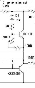
Like that ?
Thank
Gaetan
JPV said:
...
So by using a Vbe multiplier like the Leach one and force 1mA in the diode leg, we can adjust for the right operating point at room temperature and have the two diodes tracking optimally !!!
So Thermaltraks OK ??
JPV
Hello
Like that ?
Thank
Gaetan
Attachments
stinius said:If you are using a predriver and a driver, I think you have to use three ThermalTrak per side.
I'm sure everybody has seen this app. note, but I post it anyway.
Stinius
Hello
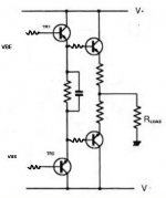
I do not use a pre-driver, here is the kind of output I use in my diy amp.
My previous diy amp was a cfp output but there was oscillations, so I did come back to a standard type II output.
Thank
Gaetan
Attachments
Re: Re: do we need stable bias current with temp in the output stage? NO
Yes but with two diodes in serie one for the NPN and one for the PNP.
The resistors must of course be calculated for the 1mA current and this depends on the current source feeding the Vbe multiplier.
If you have predriver(s) you must include diodes to take the Vbe of thedrivers into account. Here de diodes of the correspondent thermatraks ( if the driver is thermaltrak) will not track aswell and induce an overall error but these transistors should run cooler
JPV
gaetan8888 said:
Hello
Like that ?
Thank
Gaetan
Yes but with two diodes in serie one for the NPN and one for the PNP.
The resistors must of course be calculated for the 1mA current and this depends on the current source feeding the Vbe multiplier.
If you have predriver(s) you must include diodes to take the Vbe of thedrivers into account. Here de diodes of the correspondent thermatraks ( if the driver is thermaltrak) will not track aswell and induce an overall error but these transistors should run cooler
JPV
Re: Re: Re: do we need stable bias current with temp in the output stage? NO
Hello
Yes, I know, I've forgot to draw the second diodes, I did replace my image by a corrected version.
I do not use a pre-driver, you can see the type of output I use in my second images in my other post.
Thank
Gaetan
JPV said:
Yes but with two diodes in serie one for the NPN and one for the PNP.
The resistors must of course be calculated for the 1mA current and this depends on the current source feeding the Vbe multiplier.
If you have predriver(s) you must include diodes to take the Vbe of thedrivers into account. Here de diodes of the correspondent thermatraks ( if the driver is thermaltrak) will not track aswell and induce an overall error but these transistors should run cooler
JPV
Hello
Yes, I know, I've forgot to draw the second diodes, I did replace my image by a corrected version.
I do not use a pre-driver, you can see the type of output I use in my second images in my other post.
Thank
Gaetan
Re: Re: Re: Re: do we need stable bias current with temp in the output stage? NO
my comment were about the drivers and you have them. They will drift too and there we need an exact compensation.
One possibility is to use themaltraks as drivers too and use their diodes in serie with the two others in the Vbe multiplir. Because you need more voltage drop, you will need a diode ( 1Nxxx) in the base of each driver to compensate and be able to bias the Vbe multiplier transistor in the active region
The 2 extra diodes in the Vbe multiplier must track the driver
drift. One possibility is to // each diode with a resistor and have this diode working at let say 0.1 mA. The drift should then be 0.2mV/°C higher. This with a well cooled driver should make it.
You can try even 0.01ma which should give you another
-0.200mV/°C extra drift. Of course the room temperature Vbe is lower but with a well calculated potentiometer and resistors it should be possible to adjust the pot. This is without having experienced it. It is perhaps totally wrong for a reason I didn't see. Measurements and experimenting is required.
JPV
gaetan8888 said:
Hello
Yes, I know, I've forgot to draw the second diodes, I did replace my image by a corrected version.
I do not use a pre-driver, you can see the type of output I use in my second images in my other post.
Thank
Gaetan
my comment were about the drivers and you have them. They will drift too and there we need an exact compensation.
One possibility is to use themaltraks as drivers too and use their diodes in serie with the two others in the Vbe multiplir. Because you need more voltage drop, you will need a diode ( 1Nxxx) in the base of each driver to compensate and be able to bias the Vbe multiplier transistor in the active region
The 2 extra diodes in the Vbe multiplier must track the driver
drift. One possibility is to // each diode with a resistor and have this diode working at let say 0.1 mA. The drift should then be 0.2mV/°C higher. This with a well cooled driver should make it.
You can try even 0.01ma which should give you another
-0.200mV/°C extra drift. Of course the room temperature Vbe is lower but with a well calculated potentiometer and resistors it should be possible to adjust the pot. This is without having experienced it. It is perhaps totally wrong for a reason I didn't see. Measurements and experimenting is required.
JPV
Just a thought- does any one know when the original Sanken SAP transistors were introduced?
I seem to recall it was about 15 years ago, but I could be quite wrong. Any info would be much appreciated.
By the way, one advantage of all temperature-sensing output transistors that no-one seems to have mentioned is that it saves the time required to mount a bias sensing component, which can be an awkward business. In production that might help offset their greater cost.
Re: do we need stable bias current with temp in the output stage? NO
Jean-Paul/Pierre,
VERY interesting reasoning. I must look into that better, sorry I reacted so late. Hmm. What does anybody else think about this?
Jan Didden
JPV said:do we need stable bias current with temp in the output stage? NO
This seams provocative but here is why (IMHO):
Self is writing in his book that an optimal Vq ( voltage drop on Re the ouput emitter resistor) would be 26mV for minimum distortion ( in Complementary EF stage).
This is empirically found but there is more to that if you understand why.
In a previous thread I wrote a memo explaining better the original paper ( difficult to read because typo errors) of Oliver ( from HP) on this subject.
He studied analytically the non linear output resistance of a class B amplifier. It is the non linear variation of this ouput resistance with output signal which is the cause of crossover distortion.
He showed that the distortion is minimum if: gmRe =1
where gm is the transconductance of the transistor at bias Io.
What does it mean?
gmRe=1 is equivalent to (Io/Vt)Re=1 where Vt is the thermal voltage kT/q
This is the same as Io Re=Vt or the voltage drop on Re = 26mV !
But this means that if the temperature increases, so does Vt and the current should follow proportionally if we want to stay in the minimal distortion condition !!!
So, the Vbias tracking circuit should have a different Tempco than the Vbe of the outpu transistor.
Lets evaluate this Tempco for Temp from T1=300°K to T2= 375°K. for Thermaltrak transistor
first the condition IoRe=Vt means that Io2/Io1 = T2/T1
Io1 = bias at T1 and Io2 is bias at T2. This is very important In our case Io2 = 1.25 Io1 and Vt ( at T2) = 26mv * 1,25 = 32.5
If the circuit is symetrical we may calculate the Tempco of Vbias for one half. The final Vbias Tempco is twice the result.
Vbias (at T1)= Vbe ( at T1) + Io1 Re
Vbias (at T2)= ( Vbe ( at T2) + Io2 Re + Delta Vbe )
(Delta Vbe) is the increase of Vbe at constant temperature T2 to take into account that Vbe operates at a higher current Io2.
Using the diode equation Io2/Io1 = exp ( Delta Vbe/Vt)
so (Delta Vbe) = Vt ln ( Io2/Io1 )
in our case Delta Vbe = 32.5 * ln ( 1.25)= 7.25 mV
Then
Vbias ( T1) = 0.6v + 26 mV = 0.626
Vbias ( T2) = 0.6V - (2mV * 75) +32.5 mV + 7.25 mV
= 0.450 V + 39.75 mV
And Tempco Vbias =( Vbias (T2) - Vbias(T1) )/ (T2-T1)
If we replace the values Tempco = -2mV/°C + (39.75 - 26)/75
Temco = 2mV/°c - 0.183 mV/°C = - 1.817 mV/°C
NOW the good point
If we look at the specs of the diode in the thermaltrak data sheet
At low current 1ma in the diode, Tempco is about 1.81mV/°C
So by using a Vbe multiplier like the Leach one and force 1mA in the diode leg, we can adjust for the right operating point at room temperature and have the two diodes tracking optimally !!!
So Thermaltraks OK ??
JPV
Jean-Paul/Pierre,
VERY interesting reasoning. I must look into that better, sorry I reacted so late. Hmm. What does anybody else think about this?
Jan Didden
- Status
- This old topic is closed. If you want to reopen this topic, contact a moderator using the "Report Post" button.
- Home
- Amplifiers
- Solid State
- On Semi ThermalTrak