Hi everyone,
my previous thread which i think was going completely off topic so i decided to make a new thread.
I have two PCB's i salvaged from an old amplifier which i would liek to Reuse as part of my first DIY solid state amp.
Iv'e been reading up on amplifier design ont he internet and in my electronics books but I need a little help designign the input and Vas stages for the amplifier.
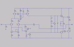
I will post what i have come up with so far for the Input stage, not really sure how well it will work or what values the components should be or what transistors to use so any suggestions for components or improvements to the design would be great. Also what would be best to use as the CCS? i have been lookign and i have found sao many diffrent designs for CCS's, just wondering what is simplest to build and what you'd all recomend.
The schematic for the pcb's are atached.
my previous thread which i think was going completely off topic so i decided to make a new thread.
I have two PCB's i salvaged from an old amplifier which i would liek to Reuse as part of my first DIY solid state amp.
Iv'e been reading up on amplifier design ont he internet and in my electronics books but I need a little help designign the input and Vas stages for the amplifier.
I will post what i have come up with so far for the Input stage, not really sure how well it will work or what values the components should be or what transistors to use so any suggestions for components or improvements to the design would be great. Also what would be best to use as the CCS? i have been lookign and i have found sao many diffrent designs for CCS's, just wondering what is simplest to build and what you'd all recomend.
The schematic for the pcb's are atached.
Attachments
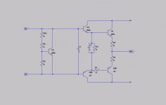
DoomPixie said:and the schematic that i have came up with so far for the input stage.
Many thanks,
Owen
looks alright
if you split up resistor R1 in two resistors
see the this image, version to the far right
http://www.dself.dsl.pipex.com/ampins/dipa/dpafig8.gif
=============
we are many that have read this investigation of distortions in power amplifiers
and learned a thing or two
http://www.dself.dsl.pipex.com/ampins/dipa/dipa.htm
The Blameless Amplifier has been viewed by thousands
and is not a bad start, from which you can make your own version
of a good audio amplifier
http://www.dself.dsl.pipex.com/ampins/dipa/dpafig33.gif
there is a lot of stuff at Douglas Self Amplifier Institute
http://www.dself.dsl.pipex.com/ampins/ampins.htm
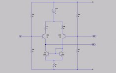
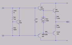
I have added the CCS circuit that they used in that distortion in power amplifiers link. that is a very usefull link, makes interesting reading.
Thanks,
Owen
edit to point out my deliberate mistake.. Q5 is the wrong way around.. Will fix next time i change the schematics. (this note is more to remind me than anything) lol
Owen
Thanks,
Owen
edit to point out my deliberate mistake.. Q5 is the wrong way around.. Will fix next time i change the schematics. (this note is more to remind me than anything) lol
Owen
Attachments
Just a little update, i have added the values of all the components on the output boards. only thing im not sure abotu is the capacitors, i used two diffrent online calculators and one said 6uF and the other said 3uF neither of which seem right judgeing by the size of them.. they are the size and shape of resistors, have a pink body and the colour bands are blue, black, orange, black, brown. Anyone have any idea what the correct value is?
Thanks,
owen
Thanks,
owen
Attachments
DoomPixie said:I have added the CCS circuit that they used in that distortion in power amplifiers link. that is a very usefull link, makes interesting reading.
Thanks,
Owen
edit to point out my deliberate mistake.. Q5 is the wrong way around.. Will fix next time i change the schematics. (this note is more to remind me than anything) lol
Owen
Hi Owen,
You might be better off to get rid of the voltage divider bias for the diff. for the sake of PSRR and use one resistor from ground for the +in side, and use a DC blocking cap for the -in side. The DC bias for the -in side comes from the output via the -feedback resistor. Looks about right otherwise.
")
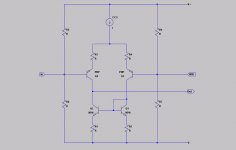
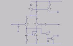
Ok, i have added a Vas stage and corrected a couple of errors i found.
CBS240: i made the changes you sugested as i understood them but im not 100% sure if thats what you meant?
anyone have any sugestions for transistors to use? i will make a list of what i have later but if they are no good i can always order more..
many thanks,
Owen
CBS240: i made the changes you sugested as i understood them but im not 100% sure if thats what you meant?
anyone have any sugestions for transistors to use? i will make a list of what i have later but if they are no good i can always order more..
many thanks,
Owen
Attachments
ok, i just checked what transistors i have here.
i have:
2N3906
2N3055
2N3700
BC107
BSX20
BD140
any of these any use in this amplifier? i dont mind buying diffrent transistors if they are needed or would be better.
looks liek i have at least 10 of each, most i have more off though. Was sure i had a load of BC108 somewhere aswell but i couldnt find them. Have a "transistor lucky bag" on the way from maplins aswell that i threw in to my last order to make the total up so i could get free postage.
many thanks,
Owen
Instead of using two diodes, use an LED as your voltage reference for the current source. They are more thermally stable and lower noise than diodes.
Add a resistor in the base leg of the current source that drives the NPN half of the amplifier.
C1 looks incorrect to me. You should have a resistor + capacitor to ground on the -VE side of the LTP, and a resistor from output to the -VE side.
AS someone already pasted a link to Doug Self's Blameless amplifier, that is a good reference point.
Ok, thanks,
I will make those changes, i thought C1 looked incorrect aswell but wasnt sure.
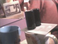
not quite sure what you mean by "Add a resistor in the base leg of the current source that drives the NPN half of the amplifier." if you mean in the output stage it will be hard because the output stages are salvaged from an old amplifier and on their own little PCB. whole point in this is that i am tryign to reuse them. mabey i should just bite the bullet and strip those boards for parts and mount all the components on a single PCB.. might be better.. i just liked how the little PCB's with the power transistors and the bias transistor mounted to the heatsink..lol..
atached is a picture of the output boards salvaged from an old fisher amplifier.
I'll go and read the up on the blameless amplifier again and put some vales into my schematic.
Many thanks,
Owen
I will make those changes, i thought C1 looked incorrect aswell but wasnt sure.
not quite sure what you mean by "Add a resistor in the base leg of the current source that drives the NPN half of the amplifier." if you mean in the output stage it will be hard because the output stages are salvaged from an old amplifier and on their own little PCB. whole point in this is that i am tryign to reuse them. mabey i should just bite the bullet and strip those boards for parts and mount all the components on a single PCB.. might be better.. i just liked how the little PCB's with the power transistors and the bias transistor mounted to the heatsink..lol..
atached is a picture of the output boards salvaged from an old fisher amplifier.
I'll go and read the up on the blameless amplifier again and put some vales into my schematic.
Many thanks,
Owen
Attachments
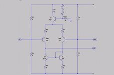
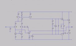
ok, i think i understood what you meant about the resistor after lookign at the blameless again. i have used the values for the resistors, etc as shown on the blameless amp not sure if they will be ok in this amp though so any sugestions for changes would be welcome. updated schematics with values atached.
I'm new to solid state amplifiers so this is like being back in school, we didnt really cover them much in my HND.
Still would liek sugestions for what transistors to use and if any of the ones i have here are suitable for anything?
how about useing 2n3906 for Q3 and Q4?
Many thanks for all your help,
owen
EDIT: forgot to atach schematic
Attachments
DoomPixie said:Ok, i have added a Vas stage and corrected a couple of errors i found.
CBS240: i made the changes you sugested as i understood them but im not 100% sure if thats what you meant?
anyone have any sugestions for transistors to use? i will make a list of what i have later but if they are no good i can always order more..
many thanks,
Owen
Hi Owen,
You got it almost right. The +in resistor is correct. The input capacitor goes to the base of this transistor, and this will set the input impeadence (Zin) to the value of that resistor (R5).
For the -input transistor, there should be a resistor from output to the base of this transistor. Then place another resistor from that base to a DC blocking capacitor to ground. This forms a voltage divider that determains the closed loop gain. To AC signals, the capacitor will conduct, but to DC it is an open circuit. This means that any DC drift will affect the diff bias greatly and it will correct for it. If you use a 47K from output to base of -in, and a 1K in series with a 47uf electrolytic Non-Polar to ground, then the AC closed loop gain will be about 47. Don't forget to place a 0.1uf mylar cap in parralell with the electrolytic because electrolytic caps have inductance as well as capacitance and this will affect audio quality.
because it could affect the bias of Q5.
Edit>>I just read post 14 and you have it right for the -in.

hi,
thanks for the replies, i think the input rails on the original were around +/- 35 or 40V because the power supply caps were rated for 50V. i'll measure the transformers supply rails tommorow.
thank's for the suggestions, i will probably use BD139/140 for the Vas and current source as i already have a load of BD140 transistors and can get the BD139's fairly cheap. But i have a lot of "lucky bag" style selections in the post so mabey i'll be lucky and have some BD139's in them.
Hopefully my new power supply capacitors will be here tommorow and then i will make the power supply PCB and build that. then i can get crackign on the rest of it.
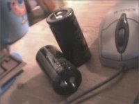
power supply capacitors arrived today! started to make a pcb for the power supply now, will go and measure the voltages the transformer is kicking out so i know what the rails will be. will post back with my findings soon pic of the cap's atached. they are 63V 4700uF Cap's to replace the 50V 2200uF that were orignally used..
thanks,
Owen
EDIT: forgot to say they are "for audio power supplies" dont know if it makes a diffrence or not but hopefully they are ok, they were pretty cheap.
pic of the cap's atached. they are 63V 4700uF Cap's to replace the 50V 2200uF that were orignally used.. thanks,
Owen
EDIT: forgot to say they are "for audio power supplies" dont know if it makes a diffrence or not but hopefully they are ok, they were pretty cheap.
Attachments
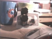
spent the last 2 hours etching the pcb for the power supply.. (dont know why it took so long)
painted the tracks on freehand with acrylic modeling paint after i decided i wanted to make them bigger than the toner transfer i had made. didnt work out too badly all in all, looks a lil tatty if you look closley but i checked it out with a multimeter and it all tests good.
drilled holes for the two cap's and then my drill's battery ran flat.
anyway, a picture speaks a thousand words. so here you are, cap's arnt soldered in , just there to show size compared to the PCB and the Mug.. looking good i think.
Thanks,
Owen
Attachments
- Status
- This old topic is closed. If you want to reopen this topic, contact a moderator using the "Report Post" button.
- Home
- Amplifiers
- Solid State
- Help designing Input and Vas stage's