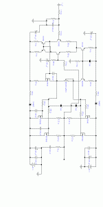
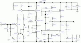
I've built this amplifier and it didn't worked!
I had about 500mV DC at the output, the bias current run from 0 to 1A and i coldn't make it lower. Injecting a signal the sound was too low, in the teorical max input voltage.
I have no idea of what it could be and how to fix it?
I had about 500mV DC at the output, the bias current run from 0 to 1A and i coldn't make it lower. Injecting a signal the sound was too low, in the teorical max input voltage.
I have no idea of what it could be and how to fix it?
Attachments
I have calculated the max inputand output signals.
And I believe, based on my project, that the current mirror feeds the next stage, but since i'm onlya rookie I can be mistaken.
I have something like 1100dB open loop gain, and I belive it is enouth, but again I can be making a huge mistake.
This amp is based on a Single output pair that I built and is working fine, this one has two pairs in the output and I removed the Vbe multiplier, the rest is the same , with only a few resistor values changed!
I'm open for anything you fellows have to say about it!
Bill Fitzpatrick said:Real cute of you to post a sideways image. We all get to crane our necks as a reward for helping?
Always with the helpful comments eh Bill.
dave
Attachments
Bill Fitzpatrick said:For sure.
You can't attach an image wider than 800 pixels. With no way to shrink it he just did the best he could. Chill out.
dave
Is the bias voltage high enough?
The output devices have threshold voltages that could be as high as 4.0 V. Your bias circuit maxes out at about 5.6 V for both sides.
However, even if the bias is too low, you should still get icky class-B performance, not nothing!
So that's probably not the problem ... hmmm...
I am curious: what is the purpose of the 1n4007 diodes?
-- mirlo
Diogo said:I have calculated the max inputand output signals.
And I believe, based on my project, that the current mirror feeds the next stage, but since i'm onlya rookie I can be mistaken.
I have something like 1100dB open loop gain, and I belive it is enouth, but again I can be making a huge mistake.
This amp is based on a Single output pair that I built and is working fine, this one has two pairs in the output and I removed the Vbe multiplier, the rest is the same , with only a few resistor values changed!
You mean 110 dB? This is slightly too much if you don't have full control over the poles (corner frequency) in each stage. 60-100 dB is a normal value. I think your main problem is around the current mirror and the MOSFET. How much can the gate voltage "move" (up and down)?
I used the diodes to avoid reverse current, it happend before when the output stage burned and the differential has gone with him, using this i can save at least the voltage and the differential stage. If it had worked I would remove it in the final prototipe.
The gain is 1100x sorry it is about 60dB.
5.6 Vgs is enought for about 6 to 7 amps, according to the datasheet!
Peranders, one of my professors believes that the main problem is in the current mirror too!
Can you help me fixing it?
PS: My first prototype of this amp wich you can see in the section burning mosfets that I have submited before was working unstable but had a signal of life.
any trouble shooting results?
Did you check for wiring errors?
Did you experiement by disconnecting the output stage, closing the loop around the last voltage gain stage and see if the circuit functions?
Did you experiment by feeding suitable level signal directly to (a lightly biased) output stage to verify that it will at least work in class B?
What currents and voltages are you seeing at various nodes? Ar any devices that should be cool instead warm/hot? Vice versa?
...
mlloyd1
No wiring errors, checked two times.
I checked all the voltage drops in the resistors before soldering the output devices, and it appeared to be right.
No i didn't tested the output stage injecting a signal in it, but i believe this stage is working fine, since it had no changes from the unstable version of this amp.
I checked all the voltage drops in the resistors before soldering the output devices, and it appeared to be right.
No i didn't tested the output stage injecting a signal in it, but i believe this stage is working fine, since it had no changes from the unstable version of this amp.
I suggest that you do DC measurements in all points. You can skip the output stage and feed back the signal directly from the second stage. If the amp still is non-working you have a fundamental problem.
The first stage must be rather fast, around 1 MHz and the second around 1-20 kHz depending on chosen open-loop gain. Much feedback-> Slower second stage.
The gain isn't 1000 as you says. The first stage current mirror has an impedance of 10-100 kohms (too tired to calculate) this makes a gain of 100-1000. The second stage has a gain of around 1000. This is too much gain and/or too fast amp.
The caps you have added at the P-channel serves no purpose at all, in fact if you wanted to "balance" the capacitancies if shuold have been on the N-channel because they (I guess) have lower internal caps. Caps are of "evil" don't add extra.
The source resistors serves a purose in BJT output stages but not in MOSFET dito. Skip them! If they should do any good they must be rather large in order to get sharing of the currents.
The series resistor to the input transistor(1k8), skip it, adds only noise (a little).
Beware also about the low drive voltage. The MOSFET's will only produce max +- 28-30 V, peak. You will loose rahter much power if the driver voltage not is increased to at least +- 50 Volts.
The series resistor to the input transistor(1k8), skip it, adds only noise (a little)
No leave it! It forms a very useful RF filter at the input and lets the preamp see a resistive load instead of the shunt capacitor.
What is Svensk for "shame on you"?
"The caps you have added at the P-channel serves no purpose at all, in fact if you wanted to "balance" the capacitancies if shuold have been on the N-channel because they (I guess) have lower internal caps. Caps are of "evil" don't add extra."
You bet!
"The source resistors serves a purose in BJT output stages but not in MOSFET dito. Skip them! If they should do any good they must be rather large in order to get sharing of the currents."
NO NO NO NO NO NO NO NO NO NO NO NO NO NO


Were you drunk Per-Anders?
They are absolutely needed for bias stability and protection from shorts on the output. They should be 1 ohm. You see some designs without them for lateral japanse mosfets, but they must be used with hexfets!
later,
Fred
No leave it! It forms a very useful RF filter at the input and lets the preamp see a resistive load instead of the shunt capacitor.

What is Svensk for "shame on you"?
"The caps you have added at the P-channel serves no purpose at all, in fact if you wanted to "balance" the capacitancies if shuold have been on the N-channel because they (I guess) have lower internal caps. Caps are of "evil" don't add extra."
You bet!

"The source resistors serves a purose in BJT output stages but not in MOSFET dito. Skip them! If they should do any good they must be rather large in order to get sharing of the currents."
NO NO NO NO NO NO NO NO NO NO NO NO NO NO


Were you drunk Per-Anders?

They are absolutely needed for bias stability and protection from shorts on the output. They should be 1 ohm. You see some designs without them for lateral japanse mosfets, but they must be used with hexfets!

later,

Fred
Re: The series resistor to the input transistor(1k8), skip it, adds only noise (a little)
Fred, you missunderstood me. I ment ONLY the 1k8 nearest to the base of the input transistor. It's very wise to have a good LP-filter at the input in order to avoid RF.
Fred Dieckmann said:No leave it! It forms a very usful RF filter at the input and lets the preamp see a resitive load instead of the shunt capacitor.
Fred, you missunderstood me. I ment ONLY the 1k8 nearest to the base of the input transistor. It's very wise to have a good LP-filter at the input in order to avoid RF.
Re: The series resistor to the input transistor(1k8), skip it, adds only noise (a little)
Fred you are in shape now, like in the good old days.
Do you really mean 1 ohms for each source resistor? The zeners works as a simple current limiter.
NO NO NO NO NO NO NO NO NO NO NO NO NO NO


Were you drunk Per-Anders? Have you tasted Zeunertz Bayer beer from north of Sweden? Like velvet on the tounge.
Fred Dieckmann said:"The source resistors serves a purose in BJT output stages but not in MOSFET dito. Skip them! If they should do any good they must be rather large in order to get sharing of the currents."
NO NO NO NO NO NO NO NO NO NO NO NO NO NO
Were you drunk Per-Anders?
They are absolutely needed for bias stability and protection from shorts on the output. They should be 1 ohm. You see some designs without them for lateral japanse mosfets, but they must be used with hexfets!
Fred you are in shape now, like in the good old days.

Do you really mean 1 ohms for each source resistor? The zeners works as a simple current limiter.
NO NO NO NO NO NO NO NO NO NO NO NO NO NO


Were you drunk Per-Anders?
 Have you tasted Zeunertz Bayer beer from north of Sweden? Like velvet on the tounge.
I don't like the current mirror driving the gate of the VAS either.
Since the gate is representing a high impedance (at DC) and the current mirror as well, there is no properly defined voltage at the gate of the VAS (I admit that this will be corrected by the NFB but I don'tlike it anyway).
Apart from that - the pole, introduced by the 100 pF capacitor and the FET's intrinsic capacitance might be much lower than intended - due to the high source impedance of the current mirror.
Regards
Charles
- Status
- This old topic is closed. If you want to reopen this topic, contact a moderator using the "Report Post" button.
- Home
- Amplifiers
- Solid State
- no working amplifier


