")
This is an experimental and easy build audio amplifier.
You can make changes and improvements in several ways.
The possibilities are endless!
Amplifier Details in this PDF:
LAB10 Audio Amplifier
More info at this website:
http://www.engga.uwo.ca/ece241b/
Attachment shows the basic circuit for
LAB10 Audio Amplifier
Attachments
.... sure! 741 as input stage isn't very exciting. LM358 is possibly even worse but almost every other opamp is betterlineup said:You can make changes and improvements in several ways.
The possibilities are endless!


op amps & darlingtons
I used to make guitar practice amps using 741,s into h/phones they worked great you could over drive them into clipping distortion for effects if you wanted.
There was a better alternative with 2 amps in the 8 leg package I think
it was a 1448 I used these to make a disco console coupled to 125
watt amplifier modules from greenweld electronics it all worked successfully they are simple and reliable devices.
regarding Darlingtons Sony use them in multiples in the output stages of their home cinema amplifiers -Sanken 2448 & 1620
Bazukaz said:Won't this amp run into thermal runaway ? I think emitter resistors are missing.
In fact this is a true Class B amp.
there is no bias in output stage ( or very very little )
'bias voltage' is set by 3 diodes ~3x0.6 = 1.8 volt
but to turn two Darlingtons on, we need, more than 4 Base-Emitter drops
normal turn on for one darlington is something like 1.0V
in this case we need a bias voltage of ~ 2.0 volt to turn two darlingtons
So 3x0.6V = 1.8V is not enough
 LF351: Jfet Input
 rinox said:OP741, uA741
Check the pinout, i think it' s not the same.
By the way, it's a good newbie project.
Pinout is standard for single Op-amp.
+input - pin3
-input - pin2
+Volt - pin7
-Volt - pin4
Output - pin6
We should not use uA741 for audio anymore.
Good replacement for uA741 could be:
NE5534
TL071
OPA134
AD797
davidallancole said:Could you not use a LED at 2.1V in place of the 3 diodes for bias?
Yes, 3 diodes or 1 LED to set Volt at that point around which
Darlingtons begin to turn on.
(The usual VBE-multiplier transistor is also a good way to achieve this.)
I dont think either choice will be very much better, than the other.
Most important will be to find something, that can set correct voltage
at around 2-10 mA current running through.
This voltage should be like 1.8-2.2 volt for most Darlingtons.
The final fine adjustment you do by changing current in diodes/LED.
That is, changing the resistors that supply diodes/LED.
A little more current (lower resistor values) = a little more voltage = more bias in output.
A good target value for idle bias in output is 10-40 mA.
This will minimize crossover distortion at Class B operation.
lineup said:
This is an experimental and easy build audio amplifier.
You can make changes and improvements in several ways.
The possibilities are endless!
Amplifier Details in this PDF:
LAB10 Audio Amplifier
More info at this website:
http://www.engga.uwo.ca/ece241b/
Attachment shows the basic circuit for
LAB10 Audio Amplifier
Excuse me Sir if I resurrect this very interesting 3D after so much time.
I am extremely interested to the "power amplifier" half of the circuit.
I have some question:
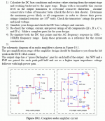
1) if I would like to use a higher (about +/-40V) voltage supply how can I calculate R4, R5 and D1,2,3 values?
2) what would be more or less the input impedance of the power stage ?
Thanks a lot and kind regards,
beppe
Re: Re: LAB10 Audio Amplifier Project
It is very much about to get correct much current in them diodes.
when they have a specific current, they will have
a voltage between Q1 input - Q2 input
that makes only a few milliampere run though Q1+Q2.
this will set what we call amplifier idle current.
How much current will be in diodes and same current in R4 + R5
will depend on how much voltage supply you use.
You can replace R4 and R5 with trimpotentiometers
and so try and adjust until only some little current comes running into Q1+Q2.
You adjust trimpotentiometers, while measure current in for example Q1.
We can not say, without practical test, exactly how much current should be in D1,D2,D3 to make the correct voltage to turn on Q1 and Q2.
We can make with simulator some guess.
But we may mostly have to adjust for reality and small production differences in diodes/transistors.
This is called production tolerances.
A power resistor can for example have value 100 ohm +- 10%. ( = 90-110 ohm )
lineup
audio lab at
http://lineup.awardspace.com/
-----------------------------------------------------
LAB10 material for download:
http://www.engga.uwo.ca/ece241b/LAB10 - PROJECT - Audio Amplifier.pdf
http://www.engga.uwo.ca/ece241b/APPENDIX241.pdf
LAB09 - prelab: http://www.engga.uwo.ca/ece241b/LAB-9 - DIFF AMPLIFIER.pdf
ECE 241B - Electrical Laboratory II
(Winter 2003)
Final Exam on Saturday, April 19
Home:
http://www.engga.uwo.ca/ece241b/
beppe61 said:
1) if I would like to use a higher (about +/-40V) voltage supply how can I calculate R4, R5 and D1,2,3 values?
2) what would be more or less the input impedance of the power stage ?
It is very much about to get correct much current in them diodes.
when they have a specific current, they will have
a voltage between Q1 input - Q2 input
that makes only a few milliampere run though Q1+Q2.
this will set what we call amplifier idle current.
How much current will be in diodes and same current in R4 + R5
will depend on how much voltage supply you use.
You can replace R4 and R5 with trimpotentiometers
and so try and adjust until only some little current comes running into Q1+Q2.
You adjust trimpotentiometers, while measure current in for example Q1.
We can not say, without practical test, exactly how much current should be in D1,D2,D3 to make the correct voltage to turn on Q1 and Q2.
We can make with simulator some guess.
But we may mostly have to adjust for reality and small production differences in diodes/transistors.
This is called production tolerances.
A power resistor can for example have value 100 ohm +- 10%. ( = 90-110 ohm )
lineup
audio lab at
http://lineup.awardspace.com/
-----------------------------------------------------
LAB10 material for download:
http://www.engga.uwo.ca/ece241b/LAB10 - PROJECT - Audio Amplifier.pdf
http://www.engga.uwo.ca/ece241b/APPENDIX241.pdf
LAB09 - prelab: http://www.engga.uwo.ca/ece241b/LAB-9 - DIFF AMPLIFIER.pdf
ECE 241B - Electrical Laboratory II
(Winter 2003)
Final Exam on Saturday, April 19
Home:
http://www.engga.uwo.ca/ece241b/
Re: Re: Re: LAB10 Audio Amplifier Project
Thank you very much Sir for your very kind and useful advice.
I have now a lot of documents to study.
I am very interested in basic design, in the hope of understanding some principles.
Your interesting web site has some very nice pictures.
Some of them are quite familiar to me (expecially the one of a desk covered by components).
Thank you very much again.
Kind regards,
beppe
lineup said:It is very much about to get correct much current in them diodes.
....
lineup
audio lab at
http://lineup.awardspace.com/
...
Thank you very much Sir for your very kind and useful advice.
I have now a lot of documents to study.
I am very interested in basic design, in the hope of understanding some principles.
Your interesting web site has some very nice pictures.
Some of them are quite familiar to me (expecially the one of a desk covered by components).
Thank you very much again.
Kind regards,
beppe
Re: Re: LAB10 Audio Amplifier Project
Just be aware Beppe that although you can increase the voltage on the power stage, it will not get you any more swing or power as the drive voltage is limited by the op-amp stage. It will just make additional heat.
beppe61 said:1) if I would like to use a higher (about +/-40V) voltage supply how can I calculate R4, R5 and D1,2,3 values?
2) what would be more or less the input impedance of the power stage ?
Thanks a lot and kind regards,
beppe
Just be aware Beppe that although you can increase the voltage on the power stage, it will not get you any more swing or power as the drive voltage is limited by the op-amp stage. It will just make additional heat.
Re: Re: Re: LAB10 Audio Amplifier Project
Thank you Sir for your kind and helpful advice.
Maybe I am wrong but the power amp section should act as a buffer. Am I wrong?
Actually I have already what I think is a good quality circuit for a voltage gain stage (it provides 6 times gain for a CD player output). Its output impedance is very low, so that it can comfortably drive low input impedance stages.
Now I need a circuit for a high current buffer stage.
In order to make a complete amp.
I am very interested in this topology because is so simple.
I would like to use:
1) +/-40V for rails and
2) a stronger TIP142/147 pair for the output.
But I am not able to calculate those blessed R4 and R5.
Thank you very much indeed.
Kind regards,
beppe
richie00boy said:
Just be aware Beppe that although you can increase the voltage on the power stage, it will not get you any more swing or power as the drive voltage is limited by the op-amp stage.
It will just make additional heat.
Thank you Sir for your kind and helpful advice.
Maybe I am wrong but the power amp section should act as a buffer. Am I wrong?
Actually I have already what I think is a good quality circuit for a voltage gain stage (it provides 6 times gain for a CD player output). Its output impedance is very low, so that it can comfortably drive low input impedance stages.
Now I need a circuit for a high current buffer stage.
In order to make a complete amp.
I am very interested in this topology because is so simple.
I would like to use:
1) +/-40V for rails and
2) a stronger TIP142/147 pair for the output.
But I am not able to calculate those blessed R4 and R5.
Thank you very much indeed.
Kind regards,
beppe
The voltage gain is not the issue, the op-amp section can only swing within a couple of volts of it's rails, so with rails limited to 18 volts by the op-amp maker, it's pointless using higher rails for the power stage.
There are also better ways to make a power buffer than what is shown here, at least where providing a good quality bias is concerned.
I am actually in the middle of prototyping an amp using TIP142/147 devices, as you inspired me to design a simple, easy to build yet good performing amp when we corresponded about the Albarry design. It's all done bar some fine tuning.
An externally hosted image should be here but it was not working when we last tested it.
looks good quality, richie00boy
I also visited your website.
Maybe you can provide some PCB for this little amp, later.
Your image is perfect!
Not too easy to catch such a good and SHARP image,
unless you are a good photographer with good camera and know what you're doing.
Regards
lineup audio website designs
http://lineup.awardspace.com/
I also visited your website.
http://www.readresearch.co.uk/
Projects Coming Soon
In development at present, to be released as bare PCBs and/or kits over the next few weeks and months
Maybe you can provide some PCB for this little amp, later.
Your image is perfect!
Not too easy to catch such a good and SHARP image,
unless you are a good photographer with good camera and know what you're doing.
Regards
lineup audio website designs
http://lineup.awardspace.com/
Thanks for the nice comments lineup, and sorry for hijacking your thread. I just have a compact digital camera and am no expert, but I spent a lot of time researching what functions/settings matter and what camera to get, and try to compose shots with my limited skills.
Once the amp has been completed and tested to my satisfaction, I will release full details on my website.
Once the amp has been completed and tested to my satisfaction, I will release full details on my website.
- Status
- This old topic is closed. If you want to reopen this topic, contact a moderator using the "Report Post" button.
- Home
- Amplifiers
- Solid State
- LAB10 Audio Amplifier Project