Hey everyone..
I have just stripped down an old integrated amp i had lying around (needed to clear some space on the shelf) and now i have some interesting little boards with the power transistors mounted on them, want to build a nice little amp out of them.
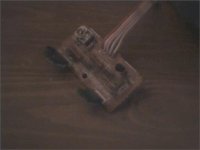
basically i have two pcb's which measure roughly 2cm x 6cm, on them are mounted a pair of toshiba transistors marked B1016 and D1407 (apparently they are 2SB1016A and 2SD1407A but i dont know if that is true or not) along with these two there is a small transistor that is also mounted so it is against the heatsink and another small transistor, some resistors and what i assume are capacitors (look like resistors with lots of coloured lines on them but marked C instead of R on the board?)
i am going to attempt to draw out the schematic for these little boards now, would appreciate idea's of what to do with them afterwards though.. oh yeh, the amp was workign when it was stripped just the control's were all a bit crackly and the EQ wasnt working right.
Owen
I have just stripped down an old integrated amp i had lying around (needed to clear some space on the shelf) and now i have some interesting little boards with the power transistors mounted on them, want to build a nice little amp out of them.
basically i have two pcb's which measure roughly 2cm x 6cm, on them are mounted a pair of toshiba transistors marked B1016 and D1407 (apparently they are 2SB1016A and 2SD1407A but i dont know if that is true or not) along with these two there is a small transistor that is also mounted so it is against the heatsink and another small transistor, some resistors and what i assume are capacitors (look like resistors with lots of coloured lines on them but marked C instead of R on the board?)
i am going to attempt to draw out the schematic for these little boards now, would appreciate idea's of what to do with them afterwards though.. oh yeh, the amp was workign when it was stripped just the control's were all a bit crackly and the EQ wasnt working right.
Owen
Japanese transistors commonly start '2S', so they don't bother printing it on the casing, so if it starts with a single letter A, B, C, D, J or K, you need to put '2S' in front of it.
As to what to do with them?, you could build an amplifier with them - but you've just broken one to get the boards, so what would be the point?.
As to what to do with them?, you could build an amplifier with them - but you've just broken one to get the boards, so what would be the point?.
well.. I was thinking about building an amplifier out of them. the amp they came from was big and bulky and didnt sound good which i reacon is in part due to the power supply.
But yeh, mabey build some amplified speakers or something..
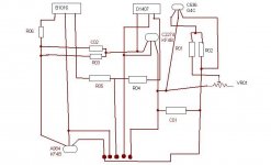
anyway, here is the schematic (if you can call it that, i had to do it in paint) i am too tired to really sit down and work it out properly at the moment.
But yeh, mabey build some amplified speakers or something..
anyway, here is the schematic (if you can call it that, i had to do it in paint) i am too tired to really sit down and work it out properly at the moment.
Attachments
Hi DoomPixie,
What you have there are the outputs, drivers and bias control circuit. You will need to build the voltage amp stage and power supply to do anything.
I don't know how much success you will have. How much study do you have under your belt? Experience? Test equipment?
It's possible a kit would be a better start. The transformer may be useful. Keep everything for now.
-Chris
I have built a few valve preamps and rebuilt and modified 2 valve amplifiers.
I have a HND in electronics engineering.
as for equipment i have a DMM, i did have an osciliscope but it broke, will probably be getting a new one in a few weeks though.
I have not thrown the rest away but it is all on a single pcb and the pwoer supply section is very unimpressive and also the phono stage opamp has had a bit of a meltdown.
It was an old Fisher amplifier.. model CA-38.
The power transformer itself looks like it is fairly decent quality compared to the rest of the amplifier..
I was only expecting that there would be a small amount of the power amps on those small pcb's and was expecting to have to diy the rest. i can find out the values of all the components on the PCB, not sure how to read the capacitor's though, havent seen any colour coded capacitors with so many colour bands on them before..
Owen
I should be able to make a more complete schematic of the boards now that i know that. I think i have located the rest of the power amp section on the main PCB aswell and it looks fairly simple, the amp wasnt at all bad it just had a few faults and a poorly designed power supply and generally tacky enclosure with broken selector switches, etc, if i can work out the rest of the power amp section i might try and etch a pcb for it and build a better power supply and see how good it is then..
All the electrolytics on board are rated at 50V and the power transformer is center tapped so i guess its probably dual rail and probably about 40V.
anyway, i am goign to go strip the rest of it down so i can get at the main PCB properly.")
Cheers,
Owen
All the electrolytics on board are rated at 50V and the power transformer is center tapped so i guess its probably dual rail and probably about 40V.
anyway, i am goign to go strip the rest of it down so i can get at the main PCB properly.
Cheers,
Owen
yeh, i remember haveing a few problems with it overheating, heatsink is nothing but a piece of aluminium that was been bent and screwed to the main PCB..lol..
iv'e been concidering building a hybrid for a while but i think i will leave that for another project. will have a look and see what i can come up with to drive these.
cheers,
OWen
iv'e been concidering building a hybrid for a while but i think i will leave that for another project. will have a look and see what i can come up with to drive these.
cheers,
OWen
i have been investigateing the main PCB and trying to work out the schematic but it is all over the place with loads of jumper wires and both channels connected together with diodes n stuff so i have given up.. i have worked out some of the pinout of the output PCB's though... center pin is the output and the pin's either side are +V and -V which i guess means the two outer pin's are the inputs from the Vas stage?
cheers,
Owen
cheers,
Owen
DoomPixie said:I have not thrown the rest away but it is all on a single pcb and the pwoer supply section is very unimpressive and also the phono stage opamp has had a bit of a meltdown.
It was an old Fisher amplifier.. model CA-38.
We did have a manual for that amplifier, but I can't find any Fisher audio manuals at work, I get the horrible feeling the entire file may have been thrown out! - but I'll keep looking.
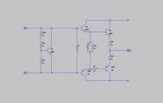
ok, i installed LTSpice and drew out the schematic for the amp board, still have to put component values in and need to find spice models for the transistors that are on it so i can simulate it when i have designed the rest of the amp. but anyway, here it is.
Attachments
lol.. is that good or bad?
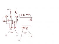
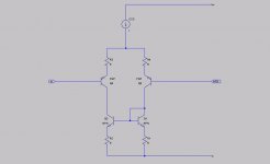
Ive been reading up and trying to work out how to drive thse boards now and from what i can tell i need to design input and Vas stages.. I was thinkign of useing somethign like this for the Input stage. Would this work after i added the CCS?
I have worked out how the CCS and Vas stages work aswell i'm just not sure how to connect them all together :/ mabey i'm just tired. got woken up too early this morning..lol
Owen
Attachments
- Status
- This old topic is closed. If you want to reopen this topic, contact a moderator using the "Report Post" button.
- Home
- Amplifiers
- Solid State
- Help finding schematics...