Folks, over the years, I have found that' less is best' for audio circuits. Now, if I were to make a low distortion amplifier for test signals, then I would do a more complex circuit, with lots of feedback. I've done it for a major test equipment manufacturer. How about an open loop bandwidth of 100,000Hz and virtually no distortion (less than .001% at 100KHz at several volts out? Good enough for you, Elso?
John, no doubt you could do it. But we as amateurs are trying to achieve the best possible sounding amps here and trying to discuss issues related to your and our input. Could we get back to discussing the schematics I presented, as I feel they can be taken a step further. In that sense it can be a meaningful exchange for all of us and especially those who contribute seriously.
What a flurry I seemed to initiate.
To return to the circuits - may I humbly suggest that the power supply needs to be considered as part of the whole, not as a separate entity. This is true of all designs, and especially true of the designs being disussed on this thread.
Earlier the ps was discussed, then 'the circuit' why not consider them together.
I agree. A few posts back I also mentioned that the power supply has not been given the attention it needs, as it is indeed a very important part of the overall design. Must admit that at first I did not consider it to be, but friends of mine who have been building amps and supplies for years have confinced me that it is.
Courage, I recall that we discussed both power supplies and servos to a great extent on this thread. It is true that this type of circuit is more sensitive to power supply variations than some others, but it is the most linear way that I know to make a fet gain stage without global or other loop feedback. That is why I used it in this preamp, but of course, it means more time and effort into the power supply.
This is not a practical circuit for mass production.
Now when it comes to why the preamp itself costs so much, it is not because of the cost of the line circuit chosen. It is because the case, pots, switches, and assembly time costs so much.
Good luck to Elso, if he can make something that sounds better, cheaper.")
This is not a practical circuit for mass production.
Now when it comes to why the preamp itself costs so much, it is not because of the cost of the line circuit chosen. It is because the case, pots, switches, and assembly time costs so much.
Good luck to Elso, if he can make something that sounds better, cheaper.
John,
Given the bias requirements of the circuit, the input stage is limited to pretty low resistance values under the Sources of the JFETs. If it were possible to use higher resistance values, would that improve the circuit's immunity (via higher CMRR) to an imperfect power supply?
Grey
Given the bias requirements of the circuit, the input stage is limited to pretty low resistance values under the Sources of the JFETs. If it were possible to use higher resistance values, would that improve the circuit's immunity (via higher CMRR) to an imperfect power supply?
Grey
John,
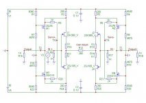
Referring to earlier posted schematic shown below, and assuming that we use an attenuator at the outputs of the DC servos (100:1 or 10:1), would their be a more apropriate and better connection-point possible for the servo +/- outputs and where in the schematic should this be applied?
Referring to earlier posted schematic shown below, and assuming that we use an attenuator at the outputs of the DC servos (100:1 or 10:1), would their be a more apropriate and better connection-point possible for the servo +/- outputs and where in the schematic should this be applied?
Attachments
John,
Allow me to rephrase my question...if there were a way to squeeze an ideal CCS between the JFET differentials--I know there's not enough room, voltage-wise, but let's pretend--would that decrease the circuit's sensitivity to real world power supply imperfections?
The higher Zout of a CCS (since we're pretending, let's go ahead and pretend that the Zout of the CCS is symmetrical [read: high] for both the N and P differentials) should increase the CMRR of both N and P differentials, thus making them less sensitive to power supply problems.
Yes, it's possible to use separate CCSs for each differential, anchoring each on the opposite rail, but that would no longer be elegant and would likely entail more noise. I like the elegance of the resistor(s) between two differentials and am willing to make the compromise, as complicated power supplies don't intimidate me. Better there than in the signal path. I've been doing odd and intricate power supplies for years, as long as it allows me to get things out of the signal path.
Grey
...........it might be tough to fit a current source between the differentials because of the voltage drops, maybe a current diode would work...........but if you look at the circuit the differentials are acting like current sources (attaching the gates and sources).....if that is true, why would you want to current source a current source.............I can agree with using current sources for the loads (drain resistors as Mr.Pass has mentioned)
Grey, I knew that you would come over to the Dark Side.
Regards,
Jam
Grey, I knew that you would come over to the Dark Side.
Regards,
Jam
Jam,
John has said precisely the same thing that I have said in many posts here over the years; some even before he became a member here. The point of my question was to make sure I understood why the circuit was, perhaps, more sensitive to power supply-related noise etc. than other topologies. It was just a thought experiment, nothing more.
I had already noted in my previous post that there's not "room" between the differentials for a current source. Again, just a thought experiment.
The front end JFETs aren't acting like current sources--especially not for each other. The Gates are tied to each other, not to the Sources. The differentials also react against a virtual ground at the midpoint of the Gate connection and another at the midpoint between the two pairs of Sources. The Source "ground" can either be made explicit by attaching it to a real ground or left floating, which does to some extent increase the apparent impedance seen by the Sources.
Given that John's goal, as I understand it, is a 0dB NFB circuit, using current sources as active loads would generate a lot of unwanted and unnecessary gain that would be a burden if you don't intend to burn it off with NFB. As such, I imagine that the idea of an active load is completely antithetical to John's intentions. And that's not to mention frequency-related compliance problems, noise, etc. Give me a good ol' resistor. Given that others here seem to feel that infinite NFB would lead to the ultimate sound, I'll let them follow their muse. For myself, the last line stage I built used a little over 7dB NFB. I'd like to get down to 0, but I'm finding it a bit of a challenge, given that I insist on at least 250kHz bandwidth in a small signal circuit. I need more experience and better parts, but I'm getting there.
Me join the Dark Side?
As Luke said..."Never!"
I will become a Jedi or bust...
Grey
- Status
- Not open for further replies.
- Home
- Amplifiers
- Solid State
- John Curl's Blowtorch preamplifier