tanh stuff
Hi Scott,
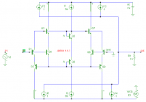
I fiddled around with this idea and results were very promising. By adding cascodes, the tail modulation circuit gets really simple.")
Regrettably one will need an exact ratio of emitter areas (~4.1), not easily achieved with discrete components.
BTW, why was this (rather obvious) variant not covered by the patent?
Cheers,
Edmond.
scott wurcer said:As Wavebourn said there is more than one way to skin a cat. Here is the AD8099 input linearizer (which does NOT compromise the noise unlike the tanh technique), US6963244. You would like Nathan a lot, he was at the Bongo dinner too
Hi Scott,
I fiddled around with this idea and results were very promising. By adding cascodes, the tail modulation circuit gets really simple.
Regrettably one will need an exact ratio of emitter areas (~4.1), not easily achieved with discrete components.
BTW, why was this (rather obvious) variant not covered by the patent?
Cheers,
Edmond.
Attachments
Re: tanh stuff
Maybe headroom? I would have to look. There is already a new variant to handle this issue. It's becoming hard to sell amplifiers that don't go to one rail on the input and both on the output.
I still think this circuit would be more amenable to just "piling on" to make the 4X diodes. You can still get good results with 4 to one and here you just have two diodes to make, in fact I think getting the right total delta-Vbe across both is good enough since this is again a translinear circuit. The 4.1 IIRC is the same ideal point as the multi-tanh.
I'm checking into the third technique.
Edmond Stuart said:
BTW, why was this (rather obvious) variant not covered by the patent?
Cheers,
Edmond.
Maybe headroom? I would have to look. There is already a new variant to handle this issue. It's becoming hard to sell amplifiers that don't go to one rail on the input and both on the output.
I still think this circuit would be more amenable to just "piling on" to make the 4X diodes. You can still get good results with 4 to one and here you just have two diodes to make, in fact I think getting the right total delta-Vbe across both is good enough since this is again a translinear circuit. The 4.1 IIRC is the same ideal point as the multi-tanh.
I'm checking into the third technique.
Re: Re: tanh stuff
Does this mean that cacoding is an obsolete technique by now?
Agreed, a ratio of 4:1 is good enough (if that's what you mean), but a THAT300 chip for example, only contains 4 match trannies, while we need 4+2=6 of them.
Of course the same ideal ratio applies, because it's essentially the same circuit. It only differs in that the modulation current (through Q5 & Q6) is directly subtracted from the tail currents (via the common emitters of the input stages), instead of via additional current mirrors (Q11,Q12,Q15 & Q16 as in fig.5 of the patent)
Also notice that in my variant, Vcb of all input and modulating trannies is kept at the same level (i.e. 0V)
Yes please.
Cheers,
Edmond.
Hi Scott,scott wurcer said:Maybe headroom? I would have to look. There is already a new variant to handle this issue. It's becoming hard to sell amplifiers that don't go to one rail on the input and both on the output.
Does this mean that cacoding is an obsolete technique by now?
I still think this circuit would be more amenable to just "piling on" to make the 4X diodes. You can still get good results with 4 to one and here you just have two diodes to make, in fact I think getting the right total delta-Vbe across both is good enough since this is again a translinear circuit.
Agreed, a ratio of 4:1 is good enough (if that's what you mean), but a THAT300 chip for example, only contains 4 match trannies, while we need 4+2=6 of them.
The 4.1 IIRC is the same ideal point as the multi-tanh.
Of course the same ideal ratio applies, because it's essentially the same circuit. It only differs in that the modulation current (through Q5 & Q6) is directly subtracted from the tail currents (via the common emitters of the input stages), instead of via additional current mirrors (Q11,Q12,Q15 & Q16 as in fig.5 of the patent)
Also notice that in my variant, Vcb of all input and modulating trannies is kept at the same level (i.e. 0V)
I'm checking into the third technique.
Yes please.
Cheers,
Edmond.
Re: Re: Re: tanh stuff
No, just the brute force techniques like those that included another level just to accomidate Ib comp transistors are not that useful anymore. Two volts from each rail does not leave much on a 5V supply .
I was wondering this morning if combining Vbe's and a thermistor of just the right TC might make one of these work in discrete form? Sort of a TC compensated area cheater. Do you know what I am refering to? Take a diode connected transistor and put a small resistor from base to collector and sample the diode voltage at the collector. I have not gone through the math on this technique. Your circuit is an excellent variant BTW it should make clear the operation to everyone.
Edmond Stuart said:
Hi Scott,
Does this mean that cacoding is an obsolete technique by now?
No, just the brute force techniques like those that included another level just to accomidate Ib comp transistors are not that useful anymore. Two volts from each rail does not leave much on a 5V supply
.I was wondering this morning if combining Vbe's and a thermistor of just the right TC might make one of these work in discrete form? Sort of a TC compensated area cheater. Do you know what I am refering to? Take a diode connected transistor and put a small resistor from base to collector and sample the diode voltage at the collector. I have not gone through the math on this technique. Your circuit is an excellent variant BTW it should make clear the operation to everyone.
Re: Re: Re: Re: tanh stuff
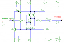
I was tinkering with that idea too, but it's not that simple. If the cuircuit also depends on resistor values, much chance that it also depends on the value of the current sources (I1 & I2), making things even more complex.
Below an example of a DIY version based on two THAT chips.
As already pointed out, the optimal value of R1 depends on Tamb AND I1 & I2!
Cheers,
Edmond.
edit: >Your circuit is an excellent variant BTW it should make clear the operation to everyone.
Thank you!
scott wurcer said:No, just the brute force techniques like those that included another level just to accomidate Ib comp transistors are not that useful anymore. Two volts from each rail does not leave much on a 5V supply
I was wondering this morning if combining Vbe's and a thermistor of just the right TC might make one of these work in discrete form? Sort of a TC compensated area cheater. Do you know what I am refering to? Take a diode connected transistor and put a small resistor from base to collector and sample the diode voltage at the collector. I have not gone through the math on this technique. Your circuit is an excellent variant BTW it should make clear the operation to everyone.
I was tinkering with that idea too, but it's not that simple. If the cuircuit also depends on resistor values, much chance that it also depends on the value of the current sources (I1 & I2), making things even more complex.
Below an example of a DIY version based on two THAT chips.
As already pointed out, the optimal value of R1 depends on Tamb AND I1 & I2!
Cheers,
Edmond.
edit: >Your circuit is an excellent variant BTW it should make clear the operation to everyone.
Thank you!
Attachments
Edmond,
From this tube hounds eyes, I can't see how that circuit can work. The output seems to be only connected to a couple of CCS's, which in turn are only connected to the rails.
Electronic telepathy perhaps?
Regards, Allen
www.vacuumstate.com
From this tube hounds eyes, I can't see how that circuit can work. The output seems to be only connected to a couple of CCS's, which in turn are only connected to the rails.
Electronic telepathy perhaps?
Regards, Allen
www.vacuumstate.com
The output seems to be only connected to a couple of CCS's
These are CCCS
tanh stuff
Hi Dimitri,
Apart from performance issues, I think that basically the idea relies on the same principle (i.e. tail current modulation).
Cheers,
Edmond.
dimitri said:Hi Scott,
What about this one? This is expired long ago.
Hi Dimitri,
Apart from performance issues, I think that basically the idea relies on the same principle (i.e. tail current modulation).
Cheers,
Edmond.
I'm just coming home from another 'pub'

Attachments


- Status
- Not open for further replies.
- Home
- Amplifiers
- Solid State
- John Curl's Blowtorch preamplifier