Well said, Demian. Everyone, even though this is not my specialty, I KNOW that we have researched and debated this for the last 30 years. Some here should get up to date, by reading up, if possible, before we have to answer very early questions and assumptions.
While I realize that not everyone here has been in audio design, or on this thread for an extended time, please don't get miffed if we don't go overboard to explain everything once again from the beginning, just because you don't want to read the prerequisites on any subject that we discuss.
While I realize that not everyone here has been in audio design, or on this thread for an extended time, please don't get miffed if we don't go overboard to explain everything once again from the beginning, just because you don't want to read the prerequisites on any subject that we discuss.
Johnloudb said:
So you're saying that jitter before the DAC makes has no effect on distortion? If that's true then digital cables should have no influence on sound. Any cable would work?
<snip>
All i´m saying is that jitter in the digital domain doesn´t have any impact as long as the data remains unchanged.
Everythings changes if digital analog conversion is done.
It depends strongly on the clock reconstruction strategy of an d/a-converter unit, if an digital cable might produce any audible difference.
And of course via the cable two quite strong hf generators are coupled, that may lead to audible differences too.
Jakob2 said:
As 1audio already pointed out, jitter has not to be signal correlated as the sources for jitter are manigfaltig and we are thinking about the more general cases.
Let's cut it short. Deterministic vs. nondeterministic jitter maps precisely (in the frequency domain) to pink noise (bandwidth limited) vs. white noise. This can be mathematically proven, see Shannon et. al. Take a look at this: http://cp.literature.agilent.com/litweb/pdf/5989-9364EN.pdf
Now, the question precisely translates to: what is the impact of pink noise on the signal spectra? Of course the answer depends on both the signal and the pink noise bandwidths, and on the amplitudes, but this doesn't make the effect non harmonic. Only the white noise, having infinite bandwidth, doesn't impact the individual signal harmonics.
Jakob2 said:
Nothing to worry about as he writes next:
"It is one very good reason for passive bandlimiting at the input of every active amplifier stage. Otherwise, the effect is cumulative - and demonstrably ugly sounding. "
")
The same can also be said of power supply artifacts. PSRR generally degrades very roughly at about the same rate as the open loop gain in a fed-back amplifier. Power supply artifacts often extend up to beyond a MHz - easily measured with a spectrum analyzer. Won't at least some of this junk mix down to the audio band?
syn08 said:
Let's cut it short. Deterministic vs. nondeterministic jitter maps precisely (in the frequency domain) to pink noise (bandwidth limited) vs. white noise. This can be mathematically proven, see Shannon et. al. Take a look at this: http://cp.literature.agilent.com/litweb/pdf/5989-9364EN.pdf
Now, the question precisely translates to: what is the impact of pink noise on the signal spectra? Of course the answer depends on both the signal and the pink noise bandwidths, and on the amplitudes, but this doesn't make the effect non harmonic. Only the white noise, having infinite bandwidth, doesn't impact the individual signal harmonics.
Please refer to page 4 of the linked agilent pdf; on the right side of the diagram two mechanism of deterministic jitter are mentioned, first data dependent and second periodic jitter (for example sinusoidal jitter).
If there is deterministic (in this example sinusoidal jitter) jitter present above the audio band, it depends on the dac structure and the signal content in the audio band which effects it will have.
The effect of sinusoidal jitter above the audio band on a audio signal of 19 kHz will be an intermodulation product inside the audio band if the sinusoidal jitter is "appropriate" .
I feel that we have a misunderstanding at this point, but do not know which way to handle it.
Jakob2 said:
Please refer to page 4 of the linked agilent pdf; on the right side of the diagram two mechanism of deterministic jitter are mentioned, first data dependent and second periodic jitter (for example sinusoidal jitter).
If there is deterministic (in this example sinusoidal jitter) above the audio band is present, it depends on the dac structure and the signal content in the audio band which effects it will have.
I feel that we have a misunderstanding at this point, but do not know which way to handle it.
I don't see any misunderstanding; sinusoidal jitter maps in the frequency space to limited bandwidth noise around the fundamental. If this bandwidth overlaps with the audio spectra (which, in turn, depends on the signal content), you got harmonic effects. Otherwise, you don't get any effect. Yes, the DAC structure may interfere here as well. At the very limit case, if "music" is a single tone outside the sinusoidal jitter limited bandwidth, you got 0 (zero) harmonic effect.
Jakob2 said:
I feel that we have a misunderstanding at this point, but do not know which way to handle it.
On a second thought, I think we have a misunderstanding here. Following your definition of "non-harmonic distortions", any intermodulation product between two uncorellated signals (one could be pink noise) leads to non-harmonic distortions, if it falls within the signal bandwidth. I disagree with this definition of "non-harmonic distortion", in fact, this concept could be as useless as the concept of "linear distortions". BTW, following your definition, is the 19+20KHz IMD test a measure of an amplifier's "non-harmonic distortions"?
Ad797
Hi Scott,
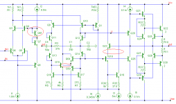
Are sure that this is the real schematic (AES preprint 3231, fig. 3a)?
There are a few things that puzzles me and/or makes no sense:
1. Q61, unless the bases of Q3 and Q4 are tied to the collector of Q61 instead of to the collector of Q7.
2. Under normal conditions Q50 is conducting, which spoils the whole thing. If I break the connection between the base of Q15 and the emitter of Q50 the circuit (almost) behaves as expected.
BTW, is Q50 meant to ease the recovery from overloading?
3. Bootstrapping the collector of Q19 instead of Q18. The latter makes more sense as no non-linear Cob loading (by Q18) of the input of the output stage.
Please, see below for my suggested mods and, of course, correct me if I'm wrong.
Regards,
Edmond.
scott wurcer said:[snip]
BTW that is the real schematic, there are no hidden surprises AFAIK except the offset null scheme might be different in reality (very lame HP plotter schematic).
Hi Scott,
Are sure that this is the real schematic (AES preprint 3231, fig. 3a)?
There are a few things that puzzles me and/or makes no sense:
1. Q61, unless the bases of Q3 and Q4 are tied to the collector of Q61 instead of to the collector of Q7.
2. Under normal conditions Q50 is conducting, which spoils the whole thing. If I break the connection between the base of Q15 and the emitter of Q50 the circuit (almost) behaves as expected.
BTW, is Q50 meant to ease the recovery from overloading?
3. Bootstrapping the collector of Q19 instead of Q18. The latter makes more sense as no non-linear Cob loading (by Q18) of the input of the output stage.
Please, see below for my suggested mods and, of course, correct me if I'm wrong.
Regards,
Edmond.
Attachments
Wavebourn said:Intermodulation between the signal and it's envelope: is it measurable? Is it harmonic?
Is hum (and other mains frequency harmonics) a form of non harmonic distortion?
syn08 said:
Is hum (and other mains frequency harmonics) a form of non harmonic distortion?
Do you mean non-linear distortions of hum?
One mechanism of what I meant, thermal changes of transfer functions by the signal itself, that may contain a hum as well, right.
Are such distortions measurable by ordinary THD measurement procedures?
http://www.aes.org/events/126/papers/session.cfm?code=P27
P27-8 Subjective and Objective Evaluation of the Audio Vacuum-Tube Amplifiers—Andrzej Dobrucki, Wroclaw University of Technology - Wroclaw, Poland; Stanislaw Maleczek, Military Institute of Engineering Technology - Wroclaw, Poland; Maurycy Kin, Wroclaw University of Technology - Wroclaw, Poland The subjective and objective evaluation of 5 high-quality vacuum-tube audio amplifiers is presented in this paper. As the reference the professional transistor amplifier has been used. The subjective evaluation has been done by the team of judges as well as with the computer-based psychoacoustic model according with PAQM protocol. The amplifiers’ sound quality assessed by the listeners is consistent with the one evaluated with the use of the psychoacoustic model. It was found that the best sound quality is obtained by vacuum-tube amplifiers, the worst—by the reference amplifier. The results of subjective evaluation are inconsistent with quality assessed by measurement of objective parameters: all amplifiers have comparable quality, but the best is the transistor amplifier because of lowest level of THD+N level.
Re: Ad797
1 and 3 make sense, I need to be at work since I don't have a copy at home. Sometimes clamp devices get drawn in a way that makes no sense.
Edmond Stuart said:
Hi Scott,
Are sure that this is the real schematic (AES preprint 3231, fig. 3a)?
There are a few things that puzzles me and/or makes no sense:
1. Q61, unless the bases of Q3 and Q4 are tied to the collector of Q61 instead of to the collector of Q7.
2. Under normal conditions Q50 is conducting, which spoils the whole thing. If I break the connection between the base of Q15 and the emitter of Q50 the circuit (almost) behaves as expected.
BTW, is Q50 meant to ease the recovery from overloading?
3. Bootstrapping the collector of Q19 instead of Q18. The latter makes more sense as no non-linear Cob loading (by Q18) of the input of the output stage.
Please, see below for my suggested mods and, of course, correct me if I'm wrong.
Regards,
Edmond.
1 and 3 make sense, I need to be at work since I don't have a copy at home. Sometimes clamp devices get drawn in a way that makes no sense.
Wavebourn said:
Do you mean non-linear distortions of hum?
One mechanism of what I meant, thermal changes of transfer functions by the signal itself, that may contain a hum as well, right.
Are such distortions measurable by ordinary THD measurement procedures?
Yes they are. This is just another non-linearity type (not even new, Self is mentioning about and its pretty famous in IC design, requiring placing the input stage devices on izotherms, etc...).
For the same reasons, an amplifier with excellent THD20 and very poor IMD 19+20KHz (or the other way around) doesn't exist.
Re: Re: Ad797
Before even looking at, I may fully agree with the conclusions. Its not even big news, it was previously reported that humas subjectively enjoy distortions (2nd harmonic?).
The problem is to objectively evaluate this kind of preferences and quantify in a general acceptable form. Then engineers could easily pick up and design according to these guidelines.
But I am afraid its going to be pretty hard to set such generally accepted guidelines, for controlled distortions content. As such, it is naïve to imagine that an amp with personalizable distortion content will ever be economically designed and manufactured.
dimitri said:
Before even looking at, I may fully agree with the conclusions. Its not even big news, it was previously reported that humas subjectively enjoy distortions (2nd harmonic?).
The problem is to objectively evaluate this kind of preferences and quantify in a general acceptable form. Then engineers could easily pick up and design according to these guidelines.
But I am afraid its going to be pretty hard to set such generally accepted guidelines, for controlled distortions content. As such, it is naïve to imagine that an amp with personalizable distortion content will ever be economically designed and manufactured.
1audio wrote
I think this is a very poor example. I believe that you are referring to spread spectrum clocks being used to to spread clock harmonics over a wider than usual spectrum in order to pass the FCC emissions test. Any decent spectrum analyser available in the past 20 years (apart from the cheap garbage based on tv tuners) can see this effect.
The spectrum anlyser is NOT at fault. The FCC test is based on the average signal level in a narrow sweeping band. This is not an example of inadequate equipment but of an outdated mandated test regime. Or rather a perfect example of commercial greed leading to some clever design methods that satisfy the letter of the law while comprehensively breaching the spririt.
A spectrum analyzer will only look at content present long enough for it to be seen by the analyzer's technology. Its conceivable that transients could pass through that the analyzer doesn't see. This trick is used a lot to get FCC approval of products that should never have been shipped.
I think this is a very poor example. I believe that you are referring to spread spectrum clocks being used to to spread clock harmonics over a wider than usual spectrum in order to pass the FCC emissions test. Any decent spectrum analyser available in the past 20 years (apart from the cheap garbage based on tv tuners) can see this effect.
The spectrum anlyser is NOT at fault. The FCC test is based on the average signal level in a narrow sweeping band. This is not an example of inadequate equipment but of an outdated mandated test regime. Or rather a perfect example of commercial greed leading to some clever design methods that satisfy the letter of the law while comprehensively breaching the spririt.
john curl said:I think we are at stage 2: 'It exists, but it is not important' (or something very close to this)
I got a ride in Jack Bybee's Bentley today. What a nice car! 650HP, and all we did was drive local streets. Naim made the auto stereo, and it was pretty good sounding.
Jay Leno's car dealer gave me a test drive in a Bentley, I thought it was a little stoggy. He also had an F1 in the shop but it was too expensive to let the riff-raff have at it (1.3M).
- Status
- Not open for further replies.
- Home
- Amplifiers
- Solid State
- John Curl's Blowtorch preamplifier