Re: RFI
Hi Edmond.
Instead of 10MHz, you might want to retry this experiment with RF carrier signals approaching the unity loop gain frequency of each amplifier.
This is where both the error signal is large and the input stage itself may still have enough gain to send plenty of the RF carrier onto the VAS. This is where marginal designs will fall flat on their face even with lower level RF signals.
Cheers,
Glen
Edmond Stuart said:AM demodulation is almost nihil. Not surprising, as the circuit is 100% symmetrical. But at strong RFI levels the THD rises considerably. That's precisely what Glen has predicted.
Cheers,
Edmond.
Hi Edmond.
Instead of 10MHz, you might want to retry this experiment with RF carrier signals approaching the unity loop gain frequency of each amplifier.
This is where both the error signal is large and the input stage itself may still have enough gain to send plenty of the RF carrier onto the VAS. This is where marginal designs will fall flat on their face even with lower level RF signals.
Cheers,
Glen
I appreciate Edmond's hard try to simulate RFI influence, but IMHO there is one of the biggest difference between real life and virtual life. I have quite a lot of time domain measurements and FFT analyzer measurements, I can post something to give Edmond a better hint.
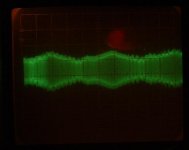
Measured at the OUTPUT of power amp, whole audio chain, single-shot trigger. Repetition frequency is pretty variable, quite low, in audio band.
Measured at the OUTPUT of power amp, whole audio chain, single-shot trigger. Repetition frequency is pretty variable, quite low, in audio band.
Attachments
Guys,
there are many other Internet stores than MCM that have the 2SJ74 and 2SK170! Even BL grdes. Both here in Europe and in the USA.
Sigurd
there are many other Internet stores than MCM that have the 2SJ74 and 2SK170! Even BL grdes. Both here in Europe and in the USA.
Sigurd
john curl said:Don't return them, but you you might have to try to buy some 2SK170 GR to best match. In any case, you can use what you have. I will explain later, if necessary. Still, it might be that Toshiba is 'cherry picking' parts for Chas Hansen, and we may not be able to get 2SJ74BL through normal channels, easily.
RFI
Hi Pavel,
I was already waiting for your input. Thanks.
So you recommend using a pulse, but what height and width?
Although I agree with you that one should measure the whole audio chain, I have to limit my simulations to various front-ends, as this thread is about the BT and variations on pre-amplifiers, NOT power amplifiers. So, in order to stay OT, I must exclude RFI effects on power output stages.
In the meanwhile, if you don't mind, I'll complete my sims using a 1MHz RFI source (on request of Glen).
Cheers,
Edmond.
PMA said:I appreciate Edmond's hard try to simulate RFI influence, but IMHO there is one of the biggest difference between real life and virtual life. I have quite a lot of time domain measurements and FFT analyzer measurements, I can post something to give Edmond a better hint.
Measured at the OUTPUT of power amp, whole audio chain, single-shot trigger. Repetition frequency is pretty variable, quite low, in audio band.
Hi Pavel,
I was already waiting for your input. Thanks.
So you recommend using a pulse, but what height and width?
Although I agree with you that one should measure the whole audio chain, I have to limit my simulations to various front-ends, as this thread is about the BT and variations on pre-amplifiers, NOT power amplifiers. So, in order to stay OT, I must exclude RFI effects on power output stages.
In the meanwhile, if you don't mind, I'll complete my sims using a 1MHz RFI source (on request of Glen).
Cheers,
Edmond.
PMA said:I appreciate Edmond's hard try to simulate RFI influence, but IMHO there is one of the biggest difference between real life and virtual life.......
Bzzzttt.
Here is a real life result. The AM waveform shown below is what get across my speakers when a ~3 meter bare wire antenna and a tank circuit consisting of a fixed capacitor in parallel with a slug tuned inductor is connected to the input of my preamp and tuned to the frequency of the 50kW AM broadcast station less than 10 kilometers away.
All discrete BJT circuitry and no audible demodulation from the speakers.
But then again, WTF would I know about RFI immunity.

Attachments
Re: Re: RFI
Hi Glen,
I've repeated the sims with 1MHz. I think a good average between a fT of Bob's EC amp (1.9MHz), blameless (550kHz) and PGP/PCP (~800kHz)
With 0.1V RFI:
................. AM: ....THD20 from ... to (in ppm)
Bob-JFET:. 2.8uV ......... 0.233 ..... 1.28
Bob-BJT:.. 1.5uV .......... no effect
Self:........ 135uV ......... 0.135 ..... 3.07
PGP:......... 61uV .......... no effect (@2mA tail current)
PGP:.......... 9uV ........... no effect (@4mA tail current)
PCP:.......... 9uV ........... no effect
With 1V RFI:
................. AM: ....THD20 from ... to (in ppm)
Bob-JFET:. 0.5mV ......... 0.233 ..... 18.2
Bob-BJT:. 0.16mV ......... no effect
Self:....... 85.3mV ......... 0.135 ..... 93.3
PGP:........ 250mV ......... 0.039 ..... 8.9 (@2mA tail current)
PGP:....... 10.6mV ......... 0.039 ..... 8.8 (@4mA tail current)
PCP:......... 78mV .......... 0.019 ..... 0.025
Clearly, Bob's front-end with BJTs in the input stage is the winner, that is, according to my simulations, for what it is worth...
And the PGP/PCP amp? Well, they obviously need good input filtering and shielding. Apparently, ultra low distortion amps have a price.
Cheers,
Edmond.
G.Kleinschmidt said:Hi Edmond.
Instead of 10MHz, you might want to retry this experiment with RF carrier signals approaching the unity loop gain frequency of each amplifier.
[snip]
Cheers,
Glen
Hi Glen,
I've repeated the sims with 1MHz. I think a good average between a fT of Bob's EC amp (1.9MHz), blameless (550kHz) and PGP/PCP (~800kHz)
With 0.1V RFI:
................. AM: ....THD20 from ... to (in ppm)
Bob-JFET:. 2.8uV ......... 0.233 ..... 1.28
Bob-BJT:.. 1.5uV .......... no effect
Self:........ 135uV ......... 0.135 ..... 3.07
PGP:......... 61uV .......... no effect (@2mA tail current)
PGP:.......... 9uV ........... no effect (@4mA tail current)
PCP:.......... 9uV ........... no effect
With 1V RFI:
................. AM: ....THD20 from ... to (in ppm)
Bob-JFET:. 0.5mV ......... 0.233 ..... 18.2
Bob-BJT:. 0.16mV ......... no effect
Self:....... 85.3mV ......... 0.135 ..... 93.3
PGP:........ 250mV ......... 0.039 ..... 8.9 (@2mA tail current)
PGP:....... 10.6mV ......... 0.039 ..... 8.8 (@4mA tail current)
PCP:......... 78mV .......... 0.019 ..... 0.025
Clearly, Bob's front-end with BJTs in the input stage is the winner, that is, according to my simulations, for what it is worth...
And the PGP/PCP amp? Well, they obviously need good input filtering and shielding. Apparently, ultra low distortion amps have a price.
Cheers,
Edmond.
WTF
WTF? Mind your words! Americans are reading your posts too and according to this msg:
http://citizen-times.com/apps/pbcs.dll/article?AID=200880625036
they might get upset by a "potentially offensive 'WTF' letter combination."
Cheers,
Edmond.
G.Kleinschmidt said:Bzzzttt.
[snip]
But then again, WTF would I know about RFI immunity.
WTF? Mind your words! Americans are reading your posts too and according to this msg:
http://citizen-times.com/apps/pbcs.dll/article?AID=200880625036
they might get upset by a "potentially offensive 'WTF' letter combination."
Cheers,
Edmond.
Re: RFI
Edmond,
I can see that you want to isolate the front end and evaluate it's
performance separately, however, a real OP stage is driving the FB
loop.
As far as I can see, you have to replicate as close as possible what
is actually happening in real life. So I would include the OP stage.
It's quite possible that the OP stage may be a show spoiler once
in the loop, so it's worth checking.
cheers
Terry
Edmond Stuart said:
Hi Pavel,
Although I agree with you that one should measure the whole audio chain, I have to limit my simulations to various front-ends, as this thread is about the BT and variations on pre-amplifiers, NOT power amplifiers. So, in order to stay OT, I must exclude RFI effects on power output stages.
Cheers,
Edmond.
Edmond,
I can see that you want to isolate the front end and evaluate it's
performance separately, however, a real OP stage is driving the FB
loop.
As far as I can see, you have to replicate as close as possible what
is actually happening in real life. So I would include the OP stage.
It's quite possible that the OP stage may be a show spoiler once
in the loop, so it's worth checking.
cheers
Terry
RFI
Hi Pavel & Terry,
Ok, that may be all true, but that wasn't the purpose of my simulation, as the debate was on BJTs versus JFETs. Therefore I've simmed them in isolation.
Maybe I'll repeat the sims, including real OP stages, but not now, as these "armchair simulations" (using Bob's words) are quite time consuming.
Cheers,
Edmond.
Re: Re: Re: RFI
Hi Edmond,
This is a nice piece of work. I would not have anticipated that the BJT version of my front-end would be more immune than the JFET. I think that in an earlier post your simulation showed that the JFET version had lower THD than the BJT version. I would also not have predicted that. Very interesting.
Cheers,
Bob
Edmond Stuart said:
Hi Glen,
I've repeated the sims with 1MHz. I think a good average between a fT of Bob's EC amp (1.9MHz), blameless (550kHz) and PGP/PCP (~800kHz)
With 0.1V RFI:
................. AM: ....THD20 from ... to (in ppm)
Bob-JFET:. 2.8uV ......... 0.233 ..... 1.28
Bob-BJT:.. 1.5uV .......... no effect
Self:........ 135uV ......... 0.135 ..... 3.07
PGP:......... 61uV .......... no effect (@2mA tail current)
PGP:.......... 9uV ........... no effect (@4mA tail current)
PCP:.......... 9uV ........... no effect
With 1V RFI:
................. AM: ....THD20 from ... to (in ppm)
Bob-JFET:. 0.5mV ......... 0.233 ..... 18.2
Bob-BJT:. 0.16mV ......... no effect
Self:....... 85.3mV ......... 0.135 ..... 93.3
PGP:........ 250mV ......... 0.039 ..... 8.9 (@2mA tail current)
PGP:....... 10.6mV ......... 0.039 ..... 8.8 (@4mA tail current)
PCP:......... 78mV .......... 0.019 ..... 0.025
Clearly, Bob's front-end with BJTs in the input stage is the winner, that is, according to my simulations, for what it is worth...
And the PGP/PCP amp? Well, they obviously need good input filtering and shielding. Apparently, ultra low distortion amps have a price.
Cheers,
Edmond.
Hi Edmond,
This is a nice piece of work. I would not have anticipated that the BJT version of my front-end would be more immune than the JFET. I think that in an earlier post your simulation showed that the JFET version had lower THD than the BJT version. I would also not have predicted that. Very interesting.
Cheers,
Bob
Re: Re: Re: Re: RFI
Cordell.
I have followed this RF immune discussion.
Eventhough this is a limited, minor issue in hifi amplifiers,
so, with today's hispeed amp inputs, like Mr Curl's approaches,
it becomes more of a concern.
? Why build fast and good ( read: excellent ) amplifiers, with extended bandwidth and have to put lowpass filter before the signal input ??
Amplifier optimal & extended internal speed & slewrate is a good thing ... in all cases.
But, if possible, we would want The Signal processed to be of higher frequency type. Putting too much of RF limits before our input device(s) is a bit contrary to some modern amplifier design preferences.
Like as our John Curl prefers to do it: No Compromise in JFET & Amplifier speed
-------
Bob Cordell, I am very pleased to know, that your work holds Quality .. in more than One Way.
As we often will find: A good amplifier design is, more than often, Good in many aspects & parameters.
Because things have been well taken care of.
By The designer.
Lineup is appreciating Robert's ( Bob Cordell ) forum contributions more and more, day by day
.. as his post's have a style & content that stand the test
.. in the long run, through the years, for our future readers
Bob Cordell said:
Hi Edmond,
This is a nice piece of work. I would not have anticipated that the BJT version of my front-end would be more immune than the JFET. I think that in an earlier post your simulation showed that the JFET version had lower THD than the BJT version. I would also not have predicted that. Very interesting.
Cheers, Bob
Cordell.
I have followed this RF immune discussion.
Eventhough this is a limited, minor issue in hifi amplifiers,
so, with today's hispeed amp inputs, like Mr Curl's approaches,
it becomes more of a concern.
? Why build fast and good ( read: excellent ) amplifiers, with extended bandwidth and have to put lowpass filter before the signal input ??
Amplifier optimal & extended internal speed & slewrate is a good thing ... in all cases.
But, if possible, we would want The Signal processed to be of higher frequency type. Putting too much of RF limits before our input device(s) is a bit contrary to some modern amplifier design preferences.
Like as our John Curl prefers to do it: No Compromise in JFET & Amplifier speed
-------
Bob Cordell, I am very pleased to know, that your work holds Quality .. in more than One Way.
As we often will find: A good amplifier design is, more than often, Good in many aspects & parameters.
Because things have been well taken care of.
By The designer.
Lineup
is appreciating Robert's ( Bob Cordell ) forum contributions more and more, day by day.. as his post's have a style & content that stand the test
.. in the long run, through the years, for our future readers
Re: Re: Re: Re: RFI
Thank you Bob.
Whether I've showed in an earlier post that the JFET version had lower THD than the BJT version, I can't remember. So, I dug in my old files, and indeed, your complete amp, i.e. including the OP stage, shows slightly less (10%) distortion with a JFET IP stage.
BTW, I didn't say in my last post that the BJT version had lower distortion, I only said that the 1MHz carrier had no effect.
Under other circumstances (10MHz carrier), JFETs peform better. Please, also look here:
http://www.diyaudio.com/forums/showthread.php?postid=1547663#post1547663
and here: http://www.diyaudio.com/forums/showthread.php?postid=1547825#post1547825
Cheers,
Edmond.
Bob Cordell said:Hi Edmond,
This is a nice piece of work. I would not have anticipated that the BJT version of my front-end would be more immune than the JFET. I think that in an earlier post your simulation showed that the JFET version had lower THD than the BJT version. I would also not have predicted that. Very interesting.
Cheers,
Bob
Thank you Bob.
Whether I've showed in an earlier post that the JFET version had lower THD than the BJT version, I can't remember. So, I dug in my old files, and indeed, your complete amp, i.e. including the OP stage, shows slightly less (10%) distortion with a JFET IP stage.
BTW, I didn't say in my last post that the BJT version had lower distortion, I only said that the 1MHz carrier had no effect.
Under other circumstances (10MHz carrier), JFETs peform better. Please, also look here:
http://www.diyaudio.com/forums/showthread.php?postid=1547663#post1547663
and here: http://www.diyaudio.com/forums/showthread.php?postid=1547825#post1547825
Cheers,
Edmond.
Re: Re: Re: Re: Re: RFI
Thanks, lineup.
I usually like to see the end-to-end bandwidth of the amplifier limited by high-quality passives than by the active closed-loop frequency response of the amplifier-proper. It just seems like a conservative approach. Note also that the input bandlimiting filters in an amplifier can be made almost arbitrarily linear-phase by employing more than one pole at increasing frequencies. This gives two benefits. First of all, multiple poles in the input filter give greater ultimate rolloff to EMI ingress at high frequencies. Secondly, the linear-phase, constant-delay approximation can be maintained. In any case, I believe it is usually best that the frequency response droop at 20 kHz be kept to about 0.1 dB or less.
One thing that I like to do is right at the RCA connector where the signal comes in, run it through a series 49.9 ohm resistor and then a shunt 100 pF capacitor to the connector ground so that the interconnect is effectively terminated in 50 ohms at very high frequencies. This, of course, is a compromise, as not all interconnects have a characteristic impedance of 50 ohms, but I think it is better than nothing, and it forms a first line of defense at the very high frequencies where things get difficult to manage.
Cheers,
Bob
lineup said:
Cordell.
I have followed this RF immune discussion.
Eventhough this is a limited, minor issue in hifi amplifiers,
so, with today's hispeed amp inputs, like Mr Curl's approaches,
it becomes more of a concern.
? Why build fast and good ( read: excellent ) amplifiers, with extended bandwidth and have to put lowpass filter before the signal input ??
Amplifier optimal & extended internal speed & slewrate is a good thing ... in all cases.
But, if possible, we would want The Signal processed to be of higher frequency type. Putting too much of RF limits before our input device(s) is a bit contrary to some modern amplifier design preferences.
Like as our John Curl prefers to do it: No Compromise in JFET & Amplifier speed
-------
Bob Cordell, I am very pleased to know, that your work holds Quality .. in more than One Way.
As we often will find: A good amplifier design is, more than often, Good in many aspects & parameters.
Because things have been well taken care of.
By The designer.
Lineup
.. as his post's have a style & content that stand the test
.. in the long run, through the years, for our future readers
Thanks, lineup.
I usually like to see the end-to-end bandwidth of the amplifier limited by high-quality passives than by the active closed-loop frequency response of the amplifier-proper. It just seems like a conservative approach. Note also that the input bandlimiting filters in an amplifier can be made almost arbitrarily linear-phase by employing more than one pole at increasing frequencies. This gives two benefits. First of all, multiple poles in the input filter give greater ultimate rolloff to EMI ingress at high frequencies. Secondly, the linear-phase, constant-delay approximation can be maintained. In any case, I believe it is usually best that the frequency response droop at 20 kHz be kept to about 0.1 dB or less.
One thing that I like to do is right at the RCA connector where the signal comes in, run it through a series 49.9 ohm resistor and then a shunt 100 pF capacitor to the connector ground so that the interconnect is effectively terminated in 50 ohms at very high frequencies. This, of course, is a compromise, as not all interconnects have a characteristic impedance of 50 ohms, but I think it is better than nothing, and it forms a first line of defense at the very high frequencies where things get difficult to manage.
Cheers,
Bob
- Status
- Not open for further replies.
- Home
- Amplifiers
- Solid State
- John Curl's Blowtorch preamplifier