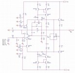
Here's the 600V/uS line preamp schematic. It looks rather complex (certainly much more complex than the 350V/uS pure opamp line preamp) but, conceptually, nothing really outstanding. What is missing in the schematic is the servo, currently implemented using a OPA132 FET input opamp in SOT-8.
For C3, C4, C5, C6, C8 and C9 it doesn't make much sense to specify the values, as they are barely lumped values only, but a combination of fixed caps and parasitics. C5 and C6 are in the low 1's pF range, C3, C4 and C9 in the low 10's of pF and C8 in the 100's of pF. They are also very strongly dependent on the opamp model. For example changing to THS4631 requires completely different values. Using OPA657, the open loop Fu was measured at around 45MHz and the OL gain at 60KHz was measured as around 90dB. Take these numbers with caution, I am not 100% confident on a precision better than +/-25%, I still have to work on better attenuators and shieldings for my OL measurement setup.
Don't bother to simulate this thing in the time domain, it won't work properly (in terms of accuracy) even if your opamp model has provisions for the supply current, so as to reflect the load current. AC simulation can be done (and some lumped values for the phase correction networks can be calculated) but this won't help much in laying out the real thing on a PCB.
PCB Gerber files (unfortunately not something that you could etch at home) and other details will be posted ASAP on my web site.
Attachments
Re: Re: PIM
Hi Glen,
Now I've simmed PIM by means of FFTs, one of the input signal and one of the output signal. (Yes I know, this is brute force, could be done more efficiently. But who cares, my CPU is water cooled ).
).
Anyhow, I compared the phase of the two fundamentals (20kHz) and, expectedly, I got a complete different result (wrt the ZC mehod):
The phase modulation (at 20kHz) was only 59 nano degrees or expressed in time: (59/360)E-9 * 50E-6 = 8.2E-15s, ie 8.2 femptoseconds, far, far less than 11 picoseconds, obtained by only looking at the zero-crossings.
Surprised? Not me!
Cheers,
Edmond.
edit: Pavel, maybe I've missed something, but what the heck has PIM to do with a dominant pole compensation?
G.Kleinschmidt said:That's a good question. ................................
Cheers,
Glen
Hi Glen,
Now I've simmed PIM by means of FFTs, one of the input signal and one of the output signal. (Yes I know, this is brute force, could be done more efficiently. But who cares, my CPU is water cooled
).Anyhow, I compared the phase of the two fundamentals (20kHz) and, expectedly, I got a complete different result (wrt the ZC mehod):
The phase modulation (at 20kHz) was only 59 nano degrees or expressed in time: (59/360)E-9 * 50E-6 = 8.2E-15s, ie 8.2 femptoseconds, far, far less than 11 picoseconds, obtained by only looking at the zero-crossings.
Surprised? Not me!
Cheers,
Edmond.
edit: Pavel, maybe I've missed something, but what the heck has PIM to do with a dominant pole compensation?
Every so often this PIM thing in relation to NFB keeps rearing its head. For those interested, read the PIM paper on my web site at www.cordellaudio.com.
I'm sure that PIM is difficult to accurately simulate, and my hat goes off to those here who have tried. I have never tried to simulate PIM in an amplifier.
During the PIM debates in 1983 I actually built a coherent IM distortion analyzer to measure PIM. I was able to show with those measurements that small open loop bandwidth does not increase PIM as long as the unity-gain frequency is held constant. The analyzer used phase locked loop techniques and coherent detection to isolate AM intermodulation distortion and phase intermodulation distortion. It basically relied on a coherent phase detector to measure PIM.
I also discussed and measured PIM in connection with my MOSFET power amplifier paper. That amplifier has lots of negative feedback. Its actual PIM measured only 0.05 ns.
I am not saying that PIM does not exist. Indeed, it exists even in amplifiers that employ no negative feedback. Nor am I saying that there is not a mechanism whereby PIM can be created by negative feedback. I discussed that mechanism in my PIM paper in 1983 and provided an explicit formula for it. Barrie Gilbert's work was little different, and his results did not conflict with mine. Nor did his results show that increased negative feedback and decreased open loop bandwidth exacerbate PIM.
In most cases, the application of negative feedback will actually reduce the total amount of PIM produced by an amplifier.
As was the case with TIM, Otala was completely wrong in suggesting that lots of negative feedback with small open loop bandwidth caused or exacerbated PIM. What matters is the unity gain bandwidth, not the open loop bandwidth.
Finally, it is very difficult for a circuit to create PIM without creating readily measurable IM and THD. The same nonlinearities are usually at work. If one deliberately put an all-pass filter in their amplifier which used a nonlinear junction capacitance for its tuning, then perhaps PIM could be created without accompanying IM.
Cheers,
Bob
john curl said:Keep it up, PMA, listen to nobody else but yourself.
Sad, very sad... This is well beyond engineering, it's already a religious war.
Q.E.D
I agree that life is boring without challenges. It seems though we choose different challenges.
Ovidiu, you advocate solid engineering approach to audio design. Baxandall and later Cordell showed that the rate of change of audio signal is very limited (taking into account frequency distribution). What was the goal in 600V/uS 4MHz line preamp design?
G.Kleinschmidt said:
What a powerfull argument.
Thank You !
It seems to me that the ' blowtorch preamplifier '
is following the design philosopy of Microsoft.
Added performance ? .... yes
Added cost ? ..................yes
Inelegance ? ..................yes
If you don't even need feedback to reach
a ' good ( hearable and measureable ) ' performance .......
Then why even slightly confuse the issue
by using it ?
OK ..... I'll switch the 2sk213 to a 2sk170 ......snoopy said:
Sir, you have avoided answering the question and your example contradicts yourself. The 1 Meg resistor used in the gate-drain circuit of the first FET is providing negative feedback !!
Somehow providing the same feedback over two stages instead of one is supposed to make it infinitely worse
Then the only thing that can be construed as
feedback will be degenerative.
Actually I've allready done that and it's about the same
but the jfet was more sensitive to power supply
fluctuations so I use the mosfet ......
But I'm gonna go back to the jfet for unambiguity on
the feedback issue ......
More like this :
An externally hosted image should be here but it was not working when we last tested it.
dimitri said:
Ovidiu, you advocate solid engineering approach to audio design. Baxandall and later Cordell showed that the rate of change of audio signal is very limited (taking into account frequency distribution). What was the goal in 600V/uS 4MHz line preamp design?
The same as in the PGP amp - exploring the limits of technology, it's my hobby.
Fortunately I am not in this sad audio industry for a living, and have no 40 years of ego to defend, so I can afford the truth.
The minimum required 'simple' sample rate alone (meaning just the sample rate never mind the other myriad issues), with zero jitter..required to equal the basic function of 'average' human hearing hovers at about 250k to 260k samples per second.
This is easily demonstrated as a trail in and of logic, in about three sentences and a simple drawing. As we learn more about sonics with respects to audio reproduction, as connected to human hearing function....we find even those numbers creeping into the 'inadequate' area.
Now..what does that mean, with regards to analog amplifier design? It tends to drift into vanishingly low %'s of distortion, in all areas and ways, as being quite critical.
Since I have not been privy to this new insight into hearing I would like to understand the reasoning behind the higher sample rate requirement.
I have had some experience with Reference Recordings Hrx 176.4 KHz recordings RR HRx and they are exceptionally good. The next two steps would be 192 (not good if CD's are the end output) 352.8 and 384, both of which really use a lot of storage space. Perhaps there is a work around, given that there really is very little acoustic information above 20 KHz in the real world.
I have had some experience with Reference Recordings Hrx 176.4 KHz recordings RR HRx and they are exceptionally good. The next two steps would be 192 (not good if CD's are the end output) 352.8 and 384, both of which really use a lot of storage space. Perhaps there is a work around, given that there really is very little acoustic information above 20 KHz in the real world.
I was on a bit of a rant that day, so pardon the slightly combative tone. It's a hair overstated and overblown..but not by much. I think you'll get the point.
Pulled from a thread on the limits of human hearing:
~~~~~~~~~~~~~~~
Take a piece of paper.
Draw a (equilateral) triangle on it.
The three points represent the listener with respect to the two speakers.
Make the speakers 10 ft apart, with the listener 10 ft back.
Now.....audiophiles have been shown to be easily able to differentiate between signals..in that 'stereoscopic sound stage' , which is strung between the speakers..where the 'image point' seems to be over, from left to right, by approximately 1 inch, and less. Now, take that 'timing' information, and then apply it to extremely rich signals, in terms of the entire note structure.
Harmonics count.
Take that information, and you add it to the fact that the ear hears, for the larger part, via the leading edge of the given transient, and it's timing differentials from harmonic transients, and the level of each.
If you go through the rather simple math..you end up with a minimal requirement to satisfy the better trained audiophiles (and I POWERFULLY stress that is is BELOW the capacity of the human ear!!! ..it is merely as well as audiophiles have managed to train themselves-nothing more)..of..get this:
500Khz sampling rate with a 20 bit word length. This as a MINIMUM. This specification is only taking into account one single aspect of the human human hearing function. One we ALL express, every single day.
As for cables, this means they must be capable of not altering a signal in any way, whatsoever..from actual DC...out to approx. 1mhz, with a +10db to -70db range of loading ..this..with ZERO phase distortion or alteration of the signal..in any way, shape or form. PERIOD. I'm not talking about a clean -3db down at 500khz, but 0db down. NO phase or complex LCR issues, at ANY point in that range. These requirements concerning harmonics and complex note structuring take these minimums up into the low Mhz range!!!!!(when it comes to 'real world-usable' examples)
This is not due to the single ear's function but as a stereoscopic pair, concerning timing issues. (the single ear is an amazing enough phase sensitive creature, with regards to complex note or energy shaping, ie temporal filtering, via complex ordering of the cilia with regards to groupings in timing activations and levels)
Which is why tube amps and turntables work. Both have extremely low inter-channel phasing issues. Totally analog. Taken to another point of analysis, it shows why digital amps are generally considered...to the more learned ear...to 'suck'.
Digital falls flat on it's face.
But the ear-brain combo can pull 'intelligence' out of a 3.5 bit deep digital signal. This does not mean that it equals hearing function, but the exact opposite. We are incredibly good at figuring out complex and dirty aural issues, but we can also 'relax' into a perfectly represented signal, as well.
This is why we can hear differences in audio equipment and wires.
I've known this simple point since 1992. I've tired to educate the industry many times. But to no avail.
Yet..the logic and the math sit there in plain sight...like a 9000lb gorilla in the middle of the room...and are ignored.
If you go through the effort of understanding this simple point, the whole entire audiophile argument makes 110% perfect sense.
~~~~~~~~~~~~~~~~~~~~~~~~~~~
1992. hmm. I've worked with that 'should be obvious' information for..uhhh..16 years now. What have I done with that? What places have I gone to? Never you mind.
What does this end up saying about amplifier design? That's for you guys to figure out. I'm not even remotely up on what to do with circuits (in the pure design sense)...but I can easily recognize some of the design components or issues that can bring fault.

- Status
- Not open for further replies.
- Home
- Amplifiers
- Solid State
- John Curl's Blowtorch preamplifier