I recommend looking at Photo #6 of a 10uf aluminum cap compared to an 8 uf polypropylene cap differentially subtracted with a (nominal) 50k load on both caps in the article: 'A Real-Time Signal Test for Capacitor Quality'. This article can be found on Walt Jung's website.
With a differential test, one can see that the signal difference between the caps lingers many times longer than the original test signal.
It looks like 'smearing' to me, but then, what do I know?")
With a differential test, one can see that the signal difference between the caps lingers many times longer than the original test signal.
It looks like 'smearing' to me, but then, what do I know?
I guess I wont talk about what is missing (my soundstage is closed) until I investigate... and this will take months. I have no opinion... only suspicions... about the DA issue in caps. On one hand I tend to think people going on about caps are just nutcases... OTOH, there seems to be a pretty fair number of nutcases... more so than speaker wires.
So...

So...
Perhpas it is once again timr for a reminder about Ken Kunderts very good paper about DA from a physical point of view
www.designers-guide.org/Modeling/da.pdf
It is the most comprehensive description i have seen about what DA is, but don't expect any discussion about audio applications there. So far, I have never until this thread seen anybody on the forum disagreeing with the linear model of DA that Kundert, Pease and other use, so whatever DA does to the sound, it is a linear effect, or it isn't caused by DA.
Actually,
I have most of Jung's books. I took him pretty seriously and still do. But, I read something he "co-authored" on a website about caps/cables or something... it was pretty... uh... uh... well, alot of really stupid adjectives... again. I think he sold/tired out (I have no problem with that...)
May be some of this stuff is true... seems like it shouldn't be rocket science to get to the facts. There is always a 20 year lag between one guy knowing the truth and the rest of us... 'sides, what do I know?
poobah said:I have most of Jung's books. I took him pretty seriously and still do. But, I read something he "co-authored" on a website about caps/cables or something... it was pretty... uh... uh... well, alot of really stupid adjectives... again. I think he sold/tired out .....
Hi poobah. You don't mean "Picking Capacitors" by any chance? That 'sell-out' article is over a quarter century old.
http://www.capacitors.com/picking_capacitors/pickcap.htm
I recommend looking at Photo #6 of a 10uf aluminum cap compared to an 8 uf polypropylene cap differentially subtracted with a (nominal) 50k load on both caps in the article: 'A Real-Time Signal Test for Capacitor Quality'. This article can be found on Walt Jung's website.
With a differential test, one can see that the signal difference between the caps lingers many times longer than the original test signal.
It looks like 'smearing' to me, but then, what do I know?
With a differential test, one can see that the signal difference between the caps lingers many times longer than the original test signal.
It looks like 'smearing' to me, but then, what do I know?

John thank you again about all the explanations, and yes your post 108 makes much sense to me, but I still have some questions.
To come back to the local regs, according to what you said and looking at the picture of the RIAA? board in the CTC, if we use a current source that “ feeds” a resistor between the gate and ground to set the voltage (as it seems to be in the picture - no leds-), the impedance seen by the fet follower gate could be quite high about 2/10k (depends on the fet current source) so in this case for low frequency noise considerations a larger value cap (so electrolytic ~ 100uF) could be necessary, nowadays will you use Leds without or with a small film cap or will you still use a resistor together with a large cap ?
The problems with lytics in the BJT regs comes I think from hard capacitive load at the emitter together with a complex impedance (small series cap inductance and low output impedance of the follower), as well as for the classical 3 terminal series regulators where sometimes a small resistor ~ 1R in series with the output lityc could improve the sound.
Now if we look at the CTC line amp board it seems that you use a MOSFET follower in the same configuration for the supplies.
Why fets in one case and mosfets in the other ?
Could you develop a little more all of that for us, please ?
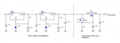
Local Fet reg.
(Sorry I forgot the small output cap in the schematic !!!)
To come back to the local regs, according to what you said and looking at the picture of the RIAA? board in the CTC, if we use a current source that “ feeds” a resistor between the gate and ground to set the voltage (as it seems to be in the picture - no leds-), the impedance seen by the fet follower gate could be quite high about 2/10k (depends on the fet current source) so in this case for low frequency noise considerations a larger value cap (so electrolytic ~ 100uF) could be necessary, nowadays will you use Leds without or with a small film cap or will you still use a resistor together with a large cap ?
The problems with lytics in the BJT regs comes I think from hard capacitive load at the emitter together with a complex impedance (small series cap inductance and low output impedance of the follower), as well as for the classical 3 terminal series regulators where sometimes a small resistor ~ 1R in series with the output lityc could improve the sound.
Now if we look at the CTC line amp board it seems that you use a MOSFET follower in the same configuration for the supplies.
Why fets in one case and mosfets in the other ?
Could you develop a little more all of that for us, please ?
Local Fet reg.
(Sorry I forgot the small output cap in the schematic !!!)
Bravo, Justcallmedad! You have discovered the topology of the input regulators of the phono input board. Good work!
This circuit is both voltage stable and low noise.
Now why jfets on the input board and mosfets everywhere else/ Well, mosfets are easier to bias and are more rugged than jfets. However, they are also more noisy.
So, I use jfets for the input board, Hitachi 1/2 amp mosfets for the second stage phono, (they are quieter than most mosfets) and Harris 1A mosfets for the line amp regulators (noisy, but easy to buy).
I might also comment that the current source (fet) and resistor load is a Norton equivalent to a zener (or LED stack). It sets a stable voltage, but you must use a low gm low noise fet so that you do not amplify the fet's noise significantly. Also, you have to select the fet and match it with an appropriate value resistor to get a repeatable voltage. This makes it harder to use than a zener, but it is much quieter.
Simplier, not better
Guess the results are much better using the resistor and fet over a cap bypassed diode. Back to the sonic signature of capacitors.
I need to review the noise levels from the active supplies in my system. Been using a lot of 3 pin regs with l-c-l-c filters on the output. Not low impedance by any means, but very quiet.
George
Hi, John
Sounds to me like a Jfet capacitor multiplier feeding the Vendetta first stage, as seen from Callmedad scheme. And the same executed with Mosfets on the second gain stage...
Well ! The voltage referencing to ground resistor fed through the Jfet used as a constant surrent source must be quite stable... A paralleled capacitor to this resistor would be a big help to shunt any voltage variation... But from the previous discussion about capacitors, I am not sure that a lytic would be your favorite in that place.... So, please, let me know what a value you would recommend, and wht tech,ology or brand if prefered...
Really sorry to say that, John, but quite a number of the parts you used from the JC-e2 era are now quasi-obsolete (but I still have a bunch, eh, eh...) : J110, J112, J175, ... and others.
I suggested to Callemedad a long channel Jfet as a current regulator... They are really hard to get in Europe now, because of Siliconix buy by Harris first, and return to Siliconix now (!)...
I heard that J203 and 2N5459 would be good candidates in this place... How is you own thinking about ? Japanese parts ?
Thanks, John
Jbaudiophile
JB, j203 is my first choice, and what I used in my Vendetta input stage. Unfortunately, they have to be sorted to .1ma in Idss and then I have to match the selected current fet with a range of 1% resistors to get the voltage right. (and people wonder why my best products cost so much) The follower is a J113 or a J175, as these are also low noise, BUT have higher transconductance for better voltage regulation. The best parts for the followers would be Toshiba low noise complementary parts, but I didn't want to 'waste' them on this application. They have almost always been hard to get, and better used in the preamp circuits directly.
The first stage regulator is not just a cap multiplier, but a Norton equivalent voltage stabilized follower, with a cap added for lower noise. Since this cap does NOT have to 'dance with the audio' so to speak, it can be just a good electrolytic cap. It doesn't even see an audio signal at any time.
You are correct that the higher level regulators are cap multipliers, as the absolute voltage is stabilized by the 3 terminal zener regulated feedback regulator.
- Status
- Not open for further replies.
- Home
- Amplifiers
- Solid State
- John Curl's Blowtorch preamplifier