john curl said:Syn08, I don't think that you understand what PMA and I find valuable about the AD825. You have your preferences, but they do not appear optimum for audio line amp design, or this question would have been settled, decades ago. Please, don't second-guess us, we know what op amps do
John,
Please spend a few moments and clarify what you find so valuable and special about the AD825. So far, I haven't heard anything but pseudo arguments.
...but they do not appear optimum for audio line amp design, or this question would have been settled, decades ago.
Unless you can explain consistently what you mean above, I'll take this as just another cheek-in-tongue dismissal.
If I missed something in your ("we") posts, I would appreciate a heads-up.
AndrewT said:I do not disagree with your premiss that BJTs can be bettered by FETs at the input. Many designers state and show the improvements to be had.
It is the mixed AC & DC coupling that I don't like.
If the pre-amp has a DC blocking cap at it's output, then the power amp must have a DC blocking cap on the NFB stage to preserve the DC balance at the inputs that we refer to and thus ensure minimal output offset.
Misusing a DC servo to allow bad topology to be incorporated is bad design in my book, even when input stage FETs are used to ameliorate the design error. and that's why a DC coupled amp and pre-amp output, need a DC servo and DC detect with output isolation.
Hi Andrew,
In some ways we seem to agree a lot, but in others I'm not so sure. I hope I am not mis-reading you, but it sounds like you are saying that a power amplifier with an AC coupling capacitor at the input and with DC-coupled NFB with servo for offset control is "misusing a DC servo to allow a bad topology to be incorporated is bad design".
In other words, you seem to be saying that if you have AC coupling on the input side, you must have a DC blocking capacitor in the return leg of the NFB side.
If this is what you are saying, I guess I must disagree. In particular, if one is using JFETs, why is the use of AC coupling on the input side with DC-coupled negative feedback on the other side (with servo for offset control) a "bad topology"?
Thanks,
Bob
john curl said:I just love those 'pseudo arguments' they are usually 'ahead of their time'.
All clear. AD825 sounds good. AD825 also improves the sound of ahead of their time recrystallized cryogenic directional solid silver cables with unbleached cotton insulation and is best in combination with ahead of their time Bybee devices.
john curl said:You should cease and desist.
Agreed, it's a waste of time.
john curl said:I don't know why an AD825 would be a special problem with I-V, but I am still hopeful to evaluate it for line amp service. The AD815 looks pretty good, also.
Hi John,
These op amps are used by Jeff Rowlands, and also in the Grace Design audio equipment.
john curl said:Anyone else with real information on capacitors?
Sorry for this late post, I'm just catching up to this thread.
Way back, we were using large Sprague mica caps in the LC harmonic trap filters of our power converters, removing the 5th, 7th, 11th and 13th harmonics of 400Hz. When Sprague discontinued these caps we tried their polysulfone types, but they just weren't stable enough over the Mil temperature range to hold the notch frequencies. Mylar caps would also drift in frequency, and overheat and exceed their internal temp limit to boot. We also tried banks of Kemet paralene caps, which were a little better. We tried GE polycarbonate caps, which were as good as paralene and available in high voltages, which was important for our application. Finally, Cornell Dubilier made a metal-cased polypropylene cap for us that was small enough to fit in the filter section of the unit, and that did the trick.
Now that Vishay owns just about everything in passive components, there would no longer be any possibility of obtaining this kind of custom packaging.
Thanks for reply and for advice, Mr. Scott and Mr.John. javascript:smilie(' ')
')
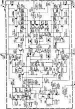
I already readed the past discussions about output coil, and is not my intention to clone this amp. I posted this schematic only for a example about a True DC amplifier, without servo, because a recently discussed subject in this thread. (a little delayed, I know...)
I don't like output coils, too. Coincidence or not, I never build an amplifier with coils, since my first one, the low feedback, unconditionally stable, trully unconventional ETI 4000 (470), from Trevor Marshall, ETI may and July 1979.
Best regards,
Marcos
')I already readed the past discussions about output coil, and is not my intention to clone this amp. I posted this schematic only for a example about a True DC amplifier, without servo, because a recently discussed subject in this thread. (a little delayed, I know...)
I don't like output coils, too. Coincidence or not, I never build an amplifier with coils, since my first one, the low feedback, unconditionally stable, trully unconventional ETI 4000 (470), from Trevor Marshall, ETI may and July 1979.
Best regards,
Marcos
Actually, DC amps of this type are fairly easy to make. However, we prefer to use a servo, because it is more temperature stable, and generally safer. In 1968 and 1969, I was a DC servo designer. This meant DC response through-out. When I started making amps for the Grateful Dead, I found that DC was just a problem, and I AC coupled it out through the feedback loop. Then I found that the large caps that we were using had distortion contributions, so I went to servos. It is 'ideal' to have a DC coupled amp, but not really practical, and REALLY expensive to do it right.
chengtaw said:Dear Scott,
What's your opinion about AD825, AD8065 and AD8067? They are ALL J-FET input Ops with SIMILIAR but DIFFERENT sounds. I did like J-FET input OPs but the appearance of LM4562 did change my mind!
Cheers,
chengtaw
Sorry, but I have no opinion on the matter. Maybe if I had some of the setups at the BA I could tell a difference. Virtually every time someone has claimed a "dramatic" difference there was something pathological going on i.e. their circuit was oscillating on high peaks or some such. I still think a major JFET vs bipolar issue is RFI, again a design issue outside of the IC (mostly).
scott wurcer said:
Sorry, but I have no opinion on the matter. Maybe if I had some of the setups at the BA I could tell a difference. Virtually every time someone has claimed a "dramatic" difference there was something pathological going on i.e. their circuit was oscillating on high peaks or some such. I still think a major JFET vs bipolar issue is RFI, again a design issue outside of the IC (mostly).
Do you mean higher susceptibility to electrical fields for Jfet because of very high input impedance or is it something else?
JPV
- Status
- Not open for further replies.
- Home
- Amplifiers
- Solid State
- John Curl's Blowtorch preamplifier