I oriented the longer leads to either the supply or the lower impedance nodes.
The lead, connected to the outward capacitor plate I also connect to the lower impedance node.
I sometimes use the vertical R's during evaluation and orientate them to give nice probe hook-up points ;-)
In instrumentation this mounting style is not preferred. Inductance issues, thermal gradients, noise pickup, mechanical stability... for regular audio I'd say it might be OK... but the BT is not about regular audio, after all.
- Klaus
In instrumentation this mounting style is not preferred. Inductance issues, thermal gradients, noise pickup, mechanical stability... for regular audio I'd say it might be OK... but the BT is not about regular audio, after all.
- Klaus
KSTR said:vertical R's during evaluation
What Mr Curl also did, judging from the tied end Holco's on pictures of the line stage, replaced by higher power versions in the final units.
Can two small value series R's connected in series but horizontally on the pcb still have merits ? It's been a while i've last seen that.
is it as bad as that?PMA said:Stand up resistors are a poor practice, one gets high lead inductance of resistors.
would the opposing currents in the up and down portions tend to cancel inductance?
The folded pair is exactly the way one would wind a low inductance wirewound resistor!!!!
Taken from Analog Devices HARDWARE AND HOUSEKEEPING TECHNIQUES .pdf
Regards
James
Figure 7-8 shows (see attached) how resistor orientation can make a difference in the net thermocouple voltage. In the left diagram, standing the resistor on end in order to conserve board space will invariably cause a temperature gradient across the resistor, especially if it is dissipating any significant power. In contrast, placing the resistor flat on the PC board as shown at the right will generally eliminate the gradient.
An exception might occur, if there is end-to-end resistor airflow. For such cases, orienting the resistor axis perpendicular to the airflow will minimize this source of error, since this tends to force the resistor ends to the same temperature.
Note that this line of thinking should be extended, to include orientation of resistors on a vertically mounted PC board. In such cases, natural convection air currents tend to flow upward across the board. Again, the resistor thermal axis should be perpendicular to convection, to minimize thermocouple effects. With tiny surface mount resistors, the thermocouple effects can be less problematic, due to tighter thermal coupling between the resistor ends.
Regards
James
Attachments
PMA said:Stand up resistors are a poor practice, one gets high lead inductance of resistors.
Lead inductance? Hahaha, add DC voltage too as a result of different temps at both ends!!
It also makes a good antenna, teflon tubing or not!
AndrewT said:is it as bad as that?
It is that bad from many points of view, as already written here by many. In professional practice best avoided.
Assuming that the resistor is non-inductive, hence some variation on a helical resistive pattern on a glass or ceramic substrate, then no, the inductances going up through the body of the resistor and down through the straight lead will not cancel. They design the body of the resistor to cancel inductance, not the leads. What happens to the leads is up to the board designer.
I have used vertical resistors only once--on the very first board layout I ever did. I've never found a need to do so since. I only did one resistor per channel that time and only did that because I boxed myself in, space-wise, and couldn't orient it any other way. I've never gone back and looked at that design, but I imagine that nowadays I could probably figure out a better layout if I was patient and worked at it for a while.
Regardless of sonic or technical characteristics, a vertical resistor is at risk of mechanical damage. That's not going to be a problem if you never touch the board again, but I always run on the assumption that I will either need to modify the circuit or service it at some point. Having something sticking up in the air unnecessarily is an invitation for trouble.
Grey
QSerraTico_Tico said:Why??? What effect will that have???

I'm assuming none, other than to protect the lead and if it's a tight fit maybe keep the lead clean. As I said it will look better as well.
Relax, I'm definitely not part of the lunitic fringe, neither is John from my following his posts.
Regards, Mike.
jacco vermeulen said:Geeh, i don't know, DATubing ?
It's teflon tubing at audio frequencies, I'm not concerned.
Buss style ground ? [/B]
I make up terminology on the fly
What I'm describing is is a wide (approx 6mm) strip used instead of a point to point trace for the power returns, I try to run them under a similar sized supply trace. Sometimes it works out that I can and sometimes not. I'll try to post a image when I get home.Mike.
PMA said:Stand up resistors are a poor practice, one gets high lead inductance of resistors.
It is that bad from many points of view, as already written here by many. In professional practice best avoided.
Once again, and I'm sure to be thought of as mis-guided, I’m only dealing with audio frequencies and DC.
Think about where the need for DC to light bandwidth comes from. If you can control that, your circuits are processing audio frequencies. The layout has a big part in this.
The trade off that I’m making here is for a much tighter layout of the sensitive part of the circuit by adding an extra 5-6mm of lead on the supply side (essentially ground potential if implemented correctly) or the low-Z nodes. My take is I’ll have stability issues if my I’m wrong.
The interesting thing is, if it is a bad choice I’ll hear it or see it on the PC, then I’ll have to layout another board and confirm it. 3 boards $55. One to get it working and two to build up and listen to.
Like I said, sure to be thought of as misguided, but I'm happy trying something and seeing what happens
My main concern right now is whether or not I'm going to need a servo and how best to build one in. I can't order the boards until I'm happy.
Regards, Mike.
I think that it is important to be both flexible and creative, as well as careful with potential problems.
The use of Teflon standoffs can be very useful with very high impedances. In fact, perhaps the the best solution.
Standing up resistors, can be a useful solution in very crowded circuitry, but it too has its drawbacks. The thermocouple effect is the most novel and interesting. It, too, is a compromise.
Analog design requires weighting the benefits and the drawbacks of every approach. Perhaps more than digital design.
Why people quibble over various solutions is what puzzles me.
john curl said:I think that it is important to be both flexible and creative, as well as careful with potential problems.
Standing up resistors, can be a useful solution in very crowded circuitry, but it too has its drawbacks.
The thermocouple effect is the most novel and interesting. It, too, is a compromise.
Analog design requires weighting the benefits and the drawbacks of every approach. Perhaps more than digital design.
Why people quibble over various solutions is what puzzles me.
Why indeed! This is what I went away pondering after checking in while eating my lunch.
Build it, listen, repeat. I've been doing it for 30 years now. Got started with this while working at the same bench everyday fixing stereos when I was in college. Anything that sounded better stood out and I spent the time (as one might in his early 20's) to postulate as to why and then try to duplicate it in my own system. Still do this today... Why should I not try standing up a resistor, just because someone had an vaguely defined (applicable?) issue with it?
I have to comment on the thermocouple effect! I have a copper lead soldered to a copper trace with a minicule voltage gradient across it, then I place it on the low-Z side of the circuit (away from the gain devices. I'm guessing that it's effect is minimal. Could be wrong, I guess, but ya can't worry about everything.
I'm just looking to have a bit of intellectual fun and have a big box full of experiment remains on which I base my comments. A request was made for tips and opinions, I spoke up.
Gotta keep it real, man!
Regards, Mike.
anatech said:Hi Mike,
I've looked at that same app. note. How does it sound? Also, I haven't studied your layout. Did you build the full passive EQ version?
-Chris
Hi Chris,
I built the active/passive version. It was a coin toss decision based on always listening to fully active EQ. Sonically it's very clean, well balanced and most notably low distortion in the high frequencies. My gut thinks that it has a bit of trouble resolving low level detail; missing a bit of airyness and possible blurring over of stuff I remember being more distinct, but that could also be caused by so many other things, poor recall, etc. All in all it's actually quite good. I've enjoyed listening to it. ( I posted a picture of it a few months back).
I'm working steadily at a discrete Jfet design and when it's done I'll get more serious about dialing in the setup (arm, cartridge suspension, grounding). right now I'm just listening to music and having fun.
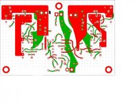
The interesting points in the layout, to me, are the low-Z supply nets and the minimalist signal path. Regulated supplys are individual loops with single outputs across the audio circuits with no output caps or bypassing needed. The FFT on the supplies are perfectly clean and below -110db (my resolution floor) the National chips do the rest.
I was experimenting with cascoding the supplies based on Walt Jungs Audio amatuer articles. Very effective. The images are also an older version than the boards I had made because the cascode is missing from the negative supply. I kind of chose the image at random.
I was looking for a reference point since I don't pretend to be anything more than servicable at circuit design; not anywhere in the league of John or Charles. I wanted to try my hand at a Jfet preamp for my MC cartridge and I need something to tell me if I was in the ballpark once I fired it up.
Regards, Mike.
Hi Mike,
I think you are on the right track on a discrete design. I've noticed similar things when using op amps, I was hoping it was gone with these types.
The very best phono stage I have ever heard is in the Marantz SC-9 or 3650 preamplifiers. It is a discrete design with J Fet input stages. When I get my digital camera back, I'll try to post some pictures of the actual board. It's built as a sub assembly and goes in it's own little space.
-Chris
anatech said:Hi Mike,
I think you are on the right track on a discrete design. I've noticed similar things when using op amps, I was hoping it was gone with these types.
The very best phono stage I have ever heard is in the Marantz SC-9 or 3650 preamplifiers. It is a discrete design with J Fet input stages. When I get my digital camera back, I'll try to post some pictures of the actual board. It's built as a sub assembly and goes in it's own little space.
-Chris
I'm anxious to finish it myself, although it will probably be another month the way my schedules been going and I still need to match FETs and assemble and test.
How old are the Marantz designs, are schematics availible? I'd be very interested in the pictures. Not many chances to see different designs these days.
Am I wrong, or did reviews use to print more inside shots of gear (and block diagrams/schematics)? I guess it's not really part of the marketing anymore to show what's under the hood.
Regards, Mike.
I am happy to see new phono stage designs. I am making two, myself, at this time. One IC, one all FET discrete.
I know from experience that discrete is better, but IC's might be OK with the NEWER topologies, such as used by National Semi.
The single stage technique, first done with tubes for decades, is not really adequate. However, a two stage design can be really successful.
I know from experience that discrete is better, but IC's might be OK with the NEWER topologies, such as used by National Semi.
The single stage technique, first done with tubes for decades, is not really adequate. However, a two stage design can be really successful.
- Status
- Not open for further replies.
- Home
- Amplifiers
- Solid State
- John Curl's Blowtorch preamplifier