I am working on a PSE studio V monoblock. One amp had its outputs shorted with another amps outputs which caused a failiure. The ex owner replaced some components and got it running again to have it die out again 3 months later. It blows the main fuses, and with the dim bulb setup lights up a 100w bulb to full steam.
Here is where I have gotten to so far. Power supply to the driver board is fine, voltage is the same as the undamaged amplifier.
This amp uses two types of outputs, both sanken. Four a1186s, and four C2837s per amp. I used the dim bulb setup and pulled outputs one at a time. I pulled all 4 2837s and still had the bulb light. The first 1186 I removed made the bulb go out and the amp come out of protection. I replaced that 1186 with the NTE correct replacment (yeah I know NTE is frowned upon). The bulb did not light after replacement so I figured I had found one of the dead soldiers.
Here is what has me confused.
When I put inputs in the first three positions back in (2837s) the light lights up. However, if I only leave one output in the far right position the bulb does NOT light. If I move that same output to another location the bulb lights up again.
Does anyone have any ideas as to whats causing this? I do not have a schematic for the amp, just a good working one for reference.
All resistors and diodes are checking out fine. I am still testing the smaller semiconductors that are on the board. Does it seem like I am on the right track?
I am a relative noob, but understand electricity pretty well. I am confident but could use some guidance.
Thanks everyone - Evan
Evan,
From each of the power output transistors you've taken out, there will be a power resistor of low value (0.1 to 0.4 ohms?) connecting to output of the amplifier. Its possible that one of them is open so that putting the transistor back in that "position" doesn't do anything.
Unfortunately this means that there may be several other problems with the amp that you still have to work out... Specially from the fact that the bulb still lights up!
Cheers!
You are correct, there are .15 ohm resistors inline with each. They are the three leg type and all seem to test out okay. I will pull them from the circut and check again though.
Another oddity that I had forgotten about. With the center leg connected in the circut, and EITHER of the base or emitter being connected = lit bulb. They did not both need to be connected
Its kind of funny because these driver boards do not have very much in the way of components. Im sure its something anybody with alot of experience can fix, but whats the fun and risk of electrocution in that??? haha.
Thanks for your help though, I do not know anyone around my area that I can bounce info off of.
Evan
240z4u said:
Another oddity that I had forgotten about. With the center leg connected in the circut, and EITHER of the base or emitter being connected = lit bulb. They did not both need to be connected
Wha? Are you sure your output trannys aren't shorted?
Cheers!
Clem
My meter does NOT indicate that they are shorted. I actually looked online at how to test these properly and they seem fine. Is a diode test only a partial indicator of a messed up output?
My light lit up even when I stuck a new NTE unit in place. Funny thing about the NTE unit is that it now meters out as a bad piece. I am not sure if i cooked it with my soldering iron or what. Its an NTE 36btw. How easy are these to burn with a soldering iron? I use a weller orange plastic soldering station set on 3.
Honestly there is a good chance I am dealing with shorted outputs that are not reacting as I would expect under out of circut testing.
Another question, there are several smaller transistors throughout the design. They do not seem to directly tie into the output transistors though. There are several that are tied to input and several that I am not sure of thier function. I attempted to test them with my transistor tester and they seem good.
Also, if one of the 1186's is still bad, could it cause funky stuff to happen when I am on the other side messing with the 2837s?
Clem, I think when I was testing with one leg disconnected it was with the toasted NTE unit. I ASSumed it was good because it was the newest.
Thanks clem!! - Evan
Hi Evan,
Diode tests are starting-point indicators, it can diagnose a "definitely dead" unit, but may not be able to indicate a leaky Collector to Emitter path. Use the resistance test of your VOM and set it to the 2Mohm range and test for leakage from C to E (in both polarities). Reading should be "open circuit" at all times.
OTOH it isn't that easy to kill a tranny, your iron should be ok as long as you aren't soldering very near to the body of the transistors.
I really suggest you try to get your hands on a schematic of the amplifier. Trying to find out what's wrong with it without knowledge of the amplifier topology isn't easy at all!
The several small transistors are the input / voltage amplification stages of the power amp. There should be another small transistor mounted on the heatsink near the power transistors - that would be the bias transistor, and if it goes bad (i.e. it is open-circuit) its likely the amplifier will exhibit the symptoms you are describing.
"Also, if one of the 1186's is still bad, could it cause funky stuff to happen when I am on the other side messing with the 2837s?"
Yes, definitely...
Cheers!
Clem
Thanks again clem!
I am going to finish testing all the small components and focus back on the output trannies.
I will also do the resistance test and see whats going on in that situation.
Your help is invaluable, I was kinda getting stuck.
I cannot find a schematic ANYWHERE, and spoke to a guy who knows the owner of PSE and he pretty much said theres no way I can get a schematic. I would hope that is not the case, I would be willing to pay for it even. Ill keep trying though. In the meanwhile, ill try to make some progress.
Thanks alot buddy - Evan
Best of luck then!
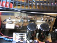
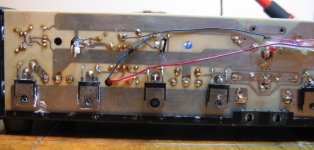
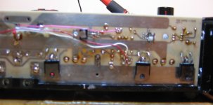
If you have a digital camera, take a pic of the top and bottom of the board and post it... might able to get an idea of what kind of circuit it has, and I'm sure a lot of people on the forum can pitch in and help!
In the meantime, I agree, have a go with the transistors first... (make sure your power supply is fully discharged before attempting to test these!)
Cheers,
Clem
Yeah, discharged. I found that out. I know so well not to mess with charged caps yet I did it anyway. BLAMMO. Bout crapped my drawers. I now have bleeder resistors installed with eyelets so I can pop them on after I unplug the amp.
I will get pictures, The board is in kinda crappy shape, with a couple lifted traces compliments of myself!
You guys are the best - Evan
I will get pictures, The board is in kinda crappy shape, with a couple lifted traces compliments of myself!
You guys are the best - Evan
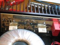
Seems like a whole lot of transistors for an output stage eh...
The latest picture shows a transistor near the toroidal power transformer, connected to some diodes, resistors and a component (two wires) mounted on the heatsink. This is your bias circuitry, which (probably) stradles across the base of the two driver transistors. The two transistors off to the left of the picture are probably pre-drivers, as the input signal seems to be routed to them. Their outputs probably wind up at the bases of the driver transistors.
The driver transistors appear to drive the output line via resistors (large gray ones), it would make sense if that junction winds up at the base of the outputs transistors..
Check if any of those blue-gray resistors are open...
Cheers!
The shot I took of the inside, near the power transformer, were of the intact amp. The thing with the two wires said something about thermal protection, and I did NOT have that bolted down. Would this cause a problem for a quick test? I have not had the amp on for more than 2 minutes with the dim-bulb.
Another wierd thing that happened, I left it on with the dim bulb, and after a minute or so the bulb went out. The amp stayed in protect but the bulb went out.
Evan
I checked those resistors, A-OK. I did replace two that had literally cooked in half when I first got the amp.
Another wierd thing that happened, I left it on with the dim bulb, and after a minute or so the bulb went out. The amp stayed in protect but the bulb went out.
Evan
I checked those resistors, A-OK. I did replace two that had literally cooked in half when I first got the amp.
Ah, so thats the thermal protection? Well, it should be ok not to have it bolted, since its supposed to cut out if the heatsink reaches too high a temp...
When you power up the amplifier does the bulb light again or does it now stay off all the time? If the latter, you may have to check those parts again as something may have decided to die.. ouch.!
Cheers
When you power up the amplifier does the bulb light again or does it now stay off all the time? If the latter, you may have to check those parts again as something may have decided to die.. ouch.!
Cheers
Could be that the protection circuit 'decides' to shut off the amp "more" after that amount of time. Hard to tell without a schematic!
Test the output voltage to ground without the output transistors in place. Should be pretty close to 0 volts - this basically looks at the health of the rest of the circuit up to the driver transistors, which appear to take an active part in driving the amplifier output line anyway.
If you have a large offset you'll have to start tracing backward to find which stage went on the blink (you can check the input signal as well)...
Cheers
UPDATE
Clem, got an update for ya.
I pulled all the outputs tonight. I have been working alot so I have not had time to play with the amp lately.
Found that the other NTE device I installed is faulty (not sure why) but found a couple other faulty devices. I specified that I could leave one of the devices in and the amp would power up. That transistor I had was definitely damaged.
How do I check the voltage to ground like you spoke of?
Also, where can I get original sanken devices? I do not know if I damaged the NTEs with my iron, but am now having doubts about quality. They are not cheap either! If I can get a reasonable price I would like to swap all of them honestly.
Thanks again clem, you helped me grab the bull by the horns on this one!
Evan
Hi Evan,
Essentially, to test from output to ground, you'd put your VOM on the output terminals of the power amplifier (i.e. the speaker output connector), or its equivalent on the PCB, if the board's out of the casing. Better do it on the board, since there's a speaker protection relay in the output path that probably will not turn on unless the amplifier's properly working...
Sorry, but I don't know where you'd be able to get original Sanken devices where you live (come to think of it, I wouldn't know where to get genuine stuff here in the Philippines too - goes to show how many fake parts there are floating on the market... !!)
Cheers!!
Clem
- Status
- This old topic is closed. If you want to reopen this topic, contact a moderator using the "Report Post" button.
- Home
- Amplifiers
- Solid State
- Attempting to fix amplifier, guidance needed please! LONG