I've got a few questions regarding the power supply caps that my amps use and how I can/should mod these.
1st let me tell you what I've got and how I use them.
2 hafler pro500's (lot like the dh500 but with ball inputs and vol control)
2 P225's
1 DH200
1 Pro2400 (whole diff animal)
I run these amps in a 4 way amped home system with active crossovers. The 500's are running the lows/mids and the smaller haflers are for the horns/tweets.
My questions:
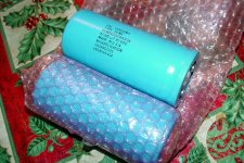
1) I picked up some Sangamo 42kuf/90VDC caps awile back (from soundvalves) to use in my 500's, but at the time I didn't reilaize the orignal caps are 100VDC. Can I use these even though they have a 10v less ratting? Or is it unsafe to do so?
I've attached a picture of the caps.
2) Since my smaller Haflers are not used for low freq is it unnessessary to beef up the pwr supply caps in these? My understanding is that this mod improves bass responce only.
PS: I've read all the threads on modding these amps will be implementing what I can understand. Awsome info in this place!
1st let me tell you what I've got and how I use them.
2 hafler pro500's (lot like the dh500 but with ball inputs and vol control)
2 P225's
1 DH200
1 Pro2400 (whole diff animal)
I run these amps in a 4 way amped home system with active crossovers. The 500's are running the lows/mids and the smaller haflers are for the horns/tweets.
My questions:
1) I picked up some Sangamo 42kuf/90VDC caps awile back (from soundvalves) to use in my 500's, but at the time I didn't reilaize the orignal caps are 100VDC. Can I use these even though they have a 10v less ratting? Or is it unsafe to do so?
I've attached a picture of the caps.
2) Since my smaller Haflers are not used for low freq is it unnessessary to beef up the pwr supply caps in these? My understanding is that this mod improves bass responce only.
PS: I've read all the threads on modding these amps will be implementing what I can understand. Awsome info in this place!
Attachments
Hi maxwedge,
You need to measure the operating voltage rails on your 500's. I am not familiar with these but I doubt the rails would be even as high as 90V.
A manufacturer usually uses capacitors of rating at least 10% higher than operating voltage with the nominal mains supply.
This is to allow for the vagaries of mains supply. So an 82V supply will be safe with 90V OR GREATER capacitors. This may be the case with Hafler 500 but the availablity was 100V rated parts.
For mid-top amps I would favour multiple paralleled smaller C's or the existing ones heavily bypassed with , say, 100uF, 1uF, 100nF, a progression of smaller types - all of equal or greater V rating.
You should not increase the rated C of the amp substantially unless you know the bridges and fuses can cope with the increased switch on surge.
Having said all that, there may be ways within the amp topology to improve the PSRR of the amp proper, and desensitize the sound to power supply artefacts. This is a more elegant approach with potential for a much bigger result but requiring design talent.
Hope that helps.
Cheers,
Greg
Thanks for the info Greg.
I'll get my dvom out see what the real voltages are at the rails and if it's under 90v then I guess these larger caps will be ok.
Yeah I'm 100% aware of the need for bypass caps, and all off these amps have none., so I'll add those at the same time.
The smaller amps have 10000uf/75v pwr caps.
I'm not an electrial tech so I pretty much need to look at some sort of guide or detailed information and I'll probably invest in some musical concept kits down the road.
Thanks again and happy new year all,
Scott

I'll get my dvom out see what the real voltages are at the rails and if it's under 90v then I guess these larger caps will be ok.
Yeah I'm 100% aware of the need for bypass caps, and all off these amps have none.
, so I'll add those at the same time.The smaller amps have 10000uf/75v pwr caps.
I'm not an electrial tech so I pretty much need to look at some sort of guide or detailed information and I'll probably invest in some musical concept kits down the road.
Thanks again and happy new year all,
Scott
A Hafler DH500 has ±93V rails, 100V is barely adequate.
The DH200 has a 10µF electrolytic input cap, and an electrolytic feedback cap. Bypass with 0.1µF film types and add 47µF 100F power supply bypass caps.
Early 500s were the same as above, later they had 2.2µF film input caps and 0.1µF film bypass on the 470µF feedback cap. They need supply bypass caps, I recommend 47µF at 160V.
The amps will sound better in the bass with the power supply bypass caps, but nowhere as 'tight' as a BJT amplifier. If you go much above 30,000µF on the main filters the rectifier will blow.
I used to have many of the DH200/220/500 series with extensive mods. I ended up with BJT amps for low end. A friend still uses my 25 year old modified DH500s for mids and highs in his tri-amp PA.
djk said:A Hafler DH500 has ±93V rails, 100V is barely adequate.
The DH200 has a 10µF electrolytic input cap, and an electrolytic feedback cap. Bypass with 0.1µF film types and add 47µF 100F power supply bypass caps.
Early 500s were the same as above, later they had 2.2µF film input caps and 0.1µF film bypass on the 470µF feedback cap. They need supply bypass caps, I recommend 47µF at 160V.
The amps will sound better in the bass with the power supply bypass caps, but nowhere as 'tight' as a BJT amplifier. If you go much above 30,000µF on the main filters the rectifier will blow.
I used to have many of the DH200/220/500 series with extensive mods. I ended up with BJT amps for low end. A friend still uses my 25 year old modified DH500s for mids and highs in his tri-amp PA.
Thanks djk, I've read a lot of your posts with great interest.
I guess I won't be using those Sangamo's on the 500's.
I've looked in the amps and all the input caps are 2mfd 50v film (as are the spec sheets I have say). The original owner of the DH200 added these in place of the electrolytic ones. Looks like these should stay. They have no by pass caps though.....Is this where the .1uf film cap should go? In parallel?
I'm not sure which one is the feedback cap but looking at the schematic for the 220, C8 is the only one with a 470mfd cap. Is that the one?
And bypass that with the .1uf film again?Thanks again.
Here is a generic amp schematic.
http://sound.westhost.com/p72-f1.gif
C1 is the input cap, C3 is the feedback cap, C7, C8 are power supply bypass caps.
C1 and C3 are the ones needing 0.1µF film bypass caps added (ones with the 2.2µF film for C1 don't need a bypass). C7 and C8 don't exist on a Hafler, they need to be added.
If you want to add C5 and C6, be very careful, it is easy to get oscillations here. I usually don't add these. If I do I use something around 0.33µF~1µF and add a 0.5 ohm resistor in series. If you don't use the resistor it will probably oscillate.
Hi djk.
I've atached a picture of the schematic for my P500 driver driver board. It's a 19c like the 220's and others use. To me it looks like the feedback cap, in this schematic, is C2. Can you confirm? This cap is a 330 pF film, fyi.
I was looking over instructions for Musical Concepts PA3C board, and for the pwr supply caps they say to bypass them with a 2.0mfd film cap and a 6800 2 watt resistor. What do you think of that resistor being there?
Thanks again,
Scott
I've atached a picture of the schematic for my P500 driver driver board. It's a 19c like the 220's and others use. To me it looks like the feedback cap, in this schematic, is C2. Can you confirm? This cap is a 330 pF film, fyi.
I was looking over instructions for Musical Concepts PA3C board, and for the pwr supply caps they say to bypass them with a 2.0mfd film cap and a 6800 2 watt resistor. What do you think of that resistor being there?
I don't need to get into that. I'll do the easy stuff 1st.Originally posted by djk
If you want to add C5 and C6, be very careful, it is easy to get oscillations here. I usually don't add these. If I do I use something around 0.33µF~1µF and add a 0.5 ohm resistor in series. If you don't use the resistor it will probably oscillate.
Thanks again,
Scott
Attachments
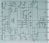
C2 is the RFI filter.
The PC19 input cap (C1) is already a film type, and the feedback cap (C8) already has a bypass (C7).
Just add some 47µF across the main filters (C404, 405) and that will help. I replace the single strand of 16ga wire that serves as a ground buss between C404, 405 with a 3/8" wide copper strap.
The PC19 input cap (C1) is already a film type, and the feedback cap (C8) already has a bypass (C7).
Just add some 47µF across the main filters (C404, 405) and that will help. I replace the single strand of 16ga wire that serves as a ground buss between C404, 405 with a 3/8" wide copper strap.
Maxwedge,
There is some confusion between posts on this thread. You have a DH-220 or DH-500, they both use the same PCB and schematic.
The early DH-200 was a threadbare design and the addition of better and a few additional passive parts helped its sound a lot. Basically, all electrolytics on the DH-200 should have bypass film caps added and many replaced C1 with a 5mF polpropylene film cap. The Dh-220 came out and incorporated into its manufactured design most of the mods published for its earlier sister, the DH-200. There is very little you can do to the DH-220 or DH-500 as they already are about as good as they can get. DJK mentioned using a larger guage wire between the two P/S which is also the system's "star" ground. After that, some improvements in the large P/S caps might help, either larger uF caps or caps that use newer technology.
Musical concepts adds the film cap to help bypass high frequency "junk" which is a common practice for many amps. MC also uses a 6800 ohom resistor to bypass each P/S electrolytic. This is a safety feature to ensure that these large caps do eventually get completely discharged before somebody's hands get in there and get a lethal shock! Also, a large cap is like a battery and it will peform better over time if completely discharged when the amp is shut down and not left to linger with a small amount of charge. Electron distribution is enhanced if the cap is completely discharged when turned off. Again, this is fairly common practice followed on some of the better amps. The bypass resistor is a safety feature and helps with the health of the capacitor and has no immediate sonic effect. MC is correct in its features.
There is little you can do to your Hafler amps except perhaps get some newer P/S caps. Relax and enjoy them.
DH amps mods
Hi Dick,
Have you fogotten about the DH-200/220 mods thread ( http://www.diyaudio.com/forums/showthread.php?postid=359323#post359323 )
and plenty of other threads on the Hafler amps?
It really depends how far someone wants to go in mods.
Dick West said:Maxwedge,
...
There is little you can do to your Hafler amps except perhaps get some newer P/S caps. Relax and enjoy them.
Hi Dick,
Have you fogotten about the DH-200/220 mods thread ( http://www.diyaudio.com/forums/showthread.php?postid=359323#post359323 )
and plenty of other threads on the Hafler amps?
It really depends how far someone wants to go in mods.
RE: Dick West
1st post
The DH200.....I'm not using at the moment but it's had it's input caps changed already, as I said in a previous post. The pro500's are what I wanted to use those Sangamo caps in but I now know I can't because their right at the limit of that amps rails. The P225's arn't used for any bass reproduction because they run the compression drivers in my system with active crossovers and my understanding is that beefed up power supply caps improves LF. Please correct me if I'm wrong about that.
The pro2400 is a lot different and has much more printed circut board layouts inside...I not much into messing with it. I just listed it with my other Haflers.
By the way, the P500's run a pair of JBL 18's and 12's for bass and mid bass.
Thanks for the info about why Musical Concepts uses those resistors and it makes a LOT of sence. I know those big caps can store a lot of energy.
I have one more question. I read posts by you people who know hafler amps in these formus and most sugest a 47uf bypass (electrolytic?) on the main power supply caps. I'm just wondering why MC uses a 2.2uf film instead??
I also want you to know (and everyone who's replied in this thread) that I'm not an electronics tech (lol), but I am a 30 year automotive tech and know how to figure things out and get it right. My hobbies are Hi performance PC's and audio.
Thanks again
Scott
1st post
Originally posted by maxwedge
1st let me tell you what I've got and how I use them.
2 hafler pro500's (lot like the dh500 but with ball inputs and vol control)
2 P225's
1 DH200
1 Pro2400 (whole diff animal)
The DH200.....I'm not using at the moment but it's had it's input caps changed already, as I said in a previous post. The pro500's are what I wanted to use those Sangamo caps in but I now know I can't because their right at the limit of that amps rails. The P225's arn't used for any bass reproduction because they run the compression drivers in my system with active crossovers and my understanding is that beefed up power supply caps improves LF. Please correct me if I'm wrong about that.
The pro2400 is a lot different and has much more printed circut board layouts inside...I not much into messing with it. I just listed it with my other Haflers.
By the way, the P500's run a pair of JBL 18's and 12's for bass and mid bass.
Thanks for the info about why Musical Concepts uses those resistors and it makes a LOT of sence. I know those big caps can store a lot of energy.
I have one more question. I read posts by you people who know hafler amps in these formus and most sugest a 47uf bypass (electrolytic?) on the main power supply caps. I'm just wondering why MC uses a 2.2uf film instead??
I also want you to know (and everyone who's replied in this thread) that I'm not an electronics tech (lol), but I am a 30 year automotive tech and know how to figure things out and get it right.
My hobbies are Hi performance PC's and audio.Thanks again
Scott
You'er 42,000 mfd caps likely have date codes back into the late 80's, early 90's. It is possible that their best use could be missiles if you just slam them on the first time. I'd install them and pull all of the fuses for the B+/-. I'd put a 25 watt light bulb in series with the line cord for current limiting the first time you turn it on. The light bulb should get real bright initially and go dim to indicate proper charging of the caps in a few seconds.
"A good practice is to also have medium value capacitors (47uf to 1000 uf for example) as close as possible (electrically) to the output power mosfets between the Drain and the power ground"
Be very careful trying this. While the power supply is best bypassed closest to the outputs, the grounds must return to where the speaker current returns. These are mutually exclusive. Most amps will turn into a power oscillator if this is not done correctly. Hafler uses some bypass caps right on the drains and grounds them on the sinks, troublesome at best.
For most people, adding a pair of 47µF right across the main filters is safe. Beyond that you will need a scope and know how to use it and sort out high frequency oscillation problems.
Re-forming old caps:
Best done on the bench. Construct a 10mA current source. Feed from the maximum rated voltage for your cap. Pre-heat the cap in an oven for 2 hours to the maximum rated temperature for your cap (85*C for most on the market). Hook up the CCS and form while hot. Don't re-form untill you are ready to use them, shelf life is only a year of so on re-formed caps not in use.
AndrewT said:Hi Djk,
re last post on reforming.
Is the elevated temperature imperative or a nice to have or simply optional?
I found this link somewhere on these forums, near the bottom of the long page is an application note on reforming electrolytics. My take is that the elevated temperature is only needed if the caps have been stored at cold temperatures.
Thanks for the tips on my old caps and will be sure to take care when of if I use them. I wouldn't have known otherwise.
I'm sure their quite old.
----------------------------------------
I also added the 6800 ohm/2 watt resistors in parallel, as MC suggests. It made a lot off sence to me after Dick West explained why. Thanks.
All my amps, except the dh200, have heavy straps across the main caps and I'll have to keep my eye open for some copper flat bar when I'm at the hardware store.
I'm sure their quite old.
----------------------------------------
I've now got my P500's pwr supply caps bypassed with 47mdf and their doing just fine.Originally posted bt djk
C2 is the RFI filter.
The PC19 input cap (C1) is already a film type, and the feedback cap (C8) already has a bypass (C7).
Just add some 47µF across the main filters (C404, 405) and that will help. I replace the single strand of 16ga wire that serves as a ground buss between C404, 405 with a 3/8" wide copper strap.
I also added the 6800 ohm/2 watt resistors in parallel, as MC suggests. It made a lot off sence to me after Dick West explained why. Thanks.All my amps, except the dh200, have heavy straps across the main caps and I'll have to keep my eye open for some copper flat bar when I'm at the hardware store.
"Is the elevated temperature imperative or a nice to have or simply optional?"
The elevated temperature allows for the electrolyte to re-distribute itself evenly throughout the capacitor during the re-forming operation, I do it with older caps.
"The one year limit;- is this only for reformed or all electrolytics?"
New parts generally have a 3~5 year shelf life. Older caps that have been reformed have about a 1 year shelf life. They will have close to a normal life if put into service right away. Normal life is a function of ambient temperature, and temperature rise due to ripple current. The cooler they are, the longer the life.
"Any possibility you can answer my thread - Reforming ?"
Didn't catch it. Please give me a link, or cut and paste my remarks as you like.
- Status
- This old topic is closed. If you want to reopen this topic, contact a moderator using the "Report Post" button.
- Home
- Amplifiers
- Solid State
- Hafler pwr supply caps