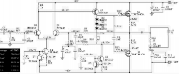
I have settled for a discrete MOSFET amp as a project for once, heres the simulation:
60W MOSFET Amp simulation
To me it looks like the diodes are the temperature bias compensation so i will put them onto the heatsink with the power fets, even tho the schemo and info about the amp doesent say anything about that.
Now i don´t have the exact devices (not even the right models in sim) for some of the parts but i figure that drivers and small signal transistors salvaged from a broken amp will work well enough.
What do you think ? as i don´t have the powerfets specced i gonna go with two pairs of the ones stated in my sim schemo.
Original schemo
You may benefit from placing those 3 diodes 1N4002
so they sense the heat from heatsink/HEXFETs.
You use 1 mA in input stage transistors, 15 mA in VAS stage.
Eventually you could double current in both stages.
Try to keep same current flow in Q1 as in Q2.
This you can do by adjusting R4.
You could also add a low value emitter resistor to Q7.
Maybe 4.7-10 Ohm.
You could add emitter resistors to Q1 and Q2, ~ 47-100 Ohm,
to get 0.100 Volt over these resistors.
Looks like it can work alright!
Without all changes I suggest.
")
so they sense the heat from heatsink/HEXFETs.
You use 1 mA in input stage transistors, 15 mA in VAS stage.
Eventually you could double current in both stages.
Try to keep same current flow in Q1 as in Q2.
This you can do by adjusting R4.
You could also add a low value emitter resistor to Q7.
Maybe 4.7-10 Ohm.
You could add emitter resistors to Q1 and Q2, ~ 47-100 Ohm,
to get 0.100 Volt over these resistors.
Looks like it can work alright!
Without all changes I suggest.
Attachments
On mosfet amps i rarely see the emmitter current sharing resistors, maybe they are not really needed. Depends on the fets used ?
What is your comments on the original shem ? I havet made anty changes in the sim other than other output fets ans substitutions for transistors i dident have models for.
What is your comments on the original shem ? I havet made anty changes in the sim other than other output fets ans substitutions for transistors i dident have models for.
Now i have slowly begun to build the thing on a piece of experiment board.
Looks like this so far:
Looks like this so far:
An externally hosted image should be here but it was not working when we last tested it.
An externally hosted image should be here but it was not working when we last tested it.
An externally hosted image should be here but it was not working when we last tested it.
- Status
- This old topic is closed. If you want to reopen this topic, contact a moderator using the "Report Post" button.