Hello all!
Hope everyone who was on holiday had a good one, and those of you not on holiday didn't work too hard")
Back to solving this oscillation conundrum...
The first thing I tried was lowering the resistance of R24 & R27 to 1 k and R26 & R25 to 10 k. This didn't make any difference.
Well, I was right. With R25 disconnected from the output and grounded instead (to ensure equal resistance to ground for both inverting and non-inverting inputs) and a 1000 uF cap across R27, the amplifier saturated to +46 V. So I cannot measure open-loop response directly.
After the failed attempt to measure open-loop response, I left R25 grounded and disconnected from the output, and connected it to the junction of D4 and D5 instead. Oscillations were not present in this configuration.
So, do you guys think this is loop stability problem? Time to play capacitor roulette?
Hope everyone who was on holiday had a good one, and those of you not on holiday didn't work too hard
Back to solving this oscillation conundrum...
The first thing I tried was lowering the resistance of R24 & R27 to 1 k and R26 & R25 to 10 k. This didn't make any difference.
poobah said:Harry I guess I don't understand why it won't run open loop... schematic as shown, with only R25 & C3 removed. I miss stuff all the time... ask EVA... can you elaborate?.
Well, I was right. With R25 disconnected from the output and grounded instead (to ensure equal resistance to ground for both inverting and non-inverting inputs) and a 1000 uF cap across R27, the amplifier saturated to +46 V. So I cannot measure open-loop response directly.
poobah said:If it is output parasitics it should show up with the junction of D4/D5 grounded.
After the failed attempt to measure open-loop response, I left R25 grounded and disconnected from the output, and connected it to the junction of D4 and D5 instead. Oscillations were not present in this configuration.
So, do you guys think this is loop stability problem? Time to play capacitor roulette?
Hey Harry,
Ok, so you've proven that the oscillation is not a parasitic in the output. That means the outputs don't have enough phase shift or feedback to to make themselves oscillate. The outputs STILL could be contributing phase shift to the total loop though...
Check out post 4 in this thread... a good way to see if the input stage is the major culprit. If it is stable, then you could suspect that output section phase shift is adding to phase shift in the loop. If it is unstable... then you cut your problem in half.
Also... somewhere along EVA posted a method to prevent DC saturation when doing a loop test... kick that one around.
Good luck
Hi poobah, thanks for the reply.
Yep, already tried that. It's the output stage poles that are the problem.
However, there are a few things that I don't quite understand if this really is a loop stability issue.
1) How come the oscillation is limited to around 5 volts pk-pk? Have I hit on almost exactly 0 dB gain margin?
2) I simulated the circuit and the simulation indicated that gain and phase margin were more than adequate.
3) Using almost exactly the same circuit, but with Sziklai output stage instead of EF, there is no loop stability problem.
Anyway, I'll try increasing the compensation capacitors and see what happens...
You mean the one in this thread about using a large capacitor? I did that.
I just did a quick rough calculation, and I reckon with the standing current that I have in the input stage, the resistors connected to the inputs would have to match to better than 1% in order to avoid saturation. I'm using 5% metal films, so presumably this is not the case and that's why the amp saturates.
poobah said:Check out post 4 in this thread... a good way to see if the input stage is the major culprit. If it is stable, then you could suspect that output section phase shift is adding to phase shift in the loop. If it is unstable... then you cut your problem in half.
Yep, already tried that. It's the output stage poles that are the problem.
However, there are a few things that I don't quite understand if this really is a loop stability issue.
1) How come the oscillation is limited to around 5 volts pk-pk? Have I hit on almost exactly 0 dB gain margin?
2) I simulated the circuit and the simulation indicated that gain and phase margin were more than adequate.
3) Using almost exactly the same circuit, but with Sziklai output stage instead of EF, there is no loop stability problem.
Anyway, I'll try increasing the compensation capacitors and see what happens...
poobah said:Also... somewhere along EVA posted a method to prevent DC saturation when doing a loop test... kick that one around.
You mean the one in this thread about using a large capacitor? I did that.
I just did a quick rough calculation, and I reckon with the standing current that I have in the input stage, the resistors connected to the inputs would have to match to better than 1% in order to avoid saturation. I'm using 5% metal films, so presumably this is not the case and that's why the amp saturates.
Hey Harry,
One thing that doesn't factor into traditional loop analysis is slew rate limiting. This is one thing that puts a cap on your absolute magnitude when oscillating.
So the step 4 thing made it stable? Proving that the output stage, while NOT parasitic, is at least a significant contributor to phase shift in the loop?
Sounds like roulette is the way to go here... remove the feedback cap entirely... then play with the feedback divider until she's just barely stable, keep track of the frequency of osc, and the feedback gain (attentuation) through this process... then you can make some assumptions about the loop gain at that point. If you can't find find the open loop function... you can at least find the closed loop 180 deg, 0 dB point. From there you can make some informed guesses as to how to compensate the beast.
You won't be able to "back out" the entire transfer function; but you will be able to nail it down around the feedback point; which is all you care about anyway...
poobah said:One thing that doesn't factor into traditional loop analysis is slew rate limiting. This is one thing that puts a cap on your absolute magnitude when oscillating.
Very good point, hadn't thought of that.
poobah said:So the step 4 thing made it stable? Proving that the output stage, while NOT parasitic, is at least a significant contributor to phase shift in the loop?
Yes.
poobah said:Sounds like roulette is the way to go here... remove the feedback cap entirely... then play with the feedback divider until she's just barely stable, keep track of the frequency of osc, and the feedback gain (attentuation) through this process... then you can make some assumptions about the loop gain at that point. If you can't find find the open loop function... you can at least find the closed loop 180 deg, 0 dB point. From there you can make some informed guesses as to how to compensate the beast.
You won't be able to "back out" the entire transfer function; but you will be able to nail it down around the feedback point; which is all you care about anyway...
Once again, thank you for your advice. I'll try this tomorrow.
Divide and conquer dude,
I am NO "audio" amp expert... I have built a lot of d4mn fine oscillators though (not on purpose).
I have found that an analytical approach can be a little better at least as a starting point. The knee jerk reaction is to start "blaming" and throw caps everywhere... 40 caps later...

I am NO "audio" amp expert... I have built a lot of d4mn fine oscillators though (not on purpose).
I have found that an analytical approach can be a little better at least as a starting point. The knee jerk reaction is to start "blaming" and throw caps everywhere... 40 caps later...
Diodes as base stoppers?
In the VAS output, this design incorporates 2x1N4148 in forward, series, before the bias scheme. This 2x1N4148 is placed before the 68ohm/1W base stoppers, before the VBE multiplier bias scheme.
What is the purpose of 2x1N4148 at VAS output here? Is it works the same as base stoppers? Why the designer uses diodes (that is 1 way path current flow) instead of R?
Attachments
The purpose of all those diodes (two in series with the base and one to the supply rail) is to clamp the base drive voltage just one diode drop below the supply rails of the ouput stage, thus preventing all three output transistors from saturating and dramatically improving clipping behaviour.
These diodes have nothing to do with frequency stabilisation and may actually reduce phase margin a bit, particularly near clipping (1N4148 are advised).
These diodes have nothing to do with frequency stabilisation and may actually reduce phase margin a bit, particularly near clipping (1N4148 are advised).
I notice that base stoppers may help to stop oscilation.
What is the mechanism with this 10R-100R in series with base that makes it stops oscilation? What is wrong with transistor's plain base?
----
Some designs "Replace" this base resistor with a B-E resistor about 470ohm (without series base resistors here).
Is this 470R B-E resistor stops oscilation by shooting at the same cause (that series base resistor targets)?
You have some basic BASE STOPPERS questions there.
Instead of starting a new topic I ask here.
What does Douglas Self say about base stopper?
I see in Blameless he has 100 Ohm stoppers for drivers (MJE340-350).
But no base stoppers to the power devices.
What does Bob Cordell know about base stoppers?
I am sure he has done some study, both for MOSFET and BIPOLAR.
Is there a possibility to make a table with the resistance we should use
for wellknown power devices?
Like for example MJL3281/1302, MJ15003/15004 etc. etc.
Please tell us more of your own experience regarding BASE STOPPERS.
Thanks
========
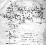
Image shows the original Blameless, by Douglas Self
An externally hosted image should be here but it was not working when we last tested it.
Last edited:
I notice that base stoppers may help to stop oscilation.
What is the mechanism with this 10R-100R in series with base that makes it stops oscilation? What is wrong with transistor's plain base?
When searching here, some members explaining about "high impedance" meeting "low impedance" terms, but I don't get it. How to understand this "impedance" terms more easily?
Some designs "Replace" this base resistor with a B-E resistor about 470ohm (without series base resistors here).
Is this 470R B-E resistor stops oscilation by shooting at the same cause (that series base resistor targets)?
Some have asked in this thread, how can a single stage EF oscillate? It is a good
thought excercise or indeed to actually build this single transistor FM transmitter:
Free Kit Plans - Build your own FM Transmitter
You don't need Q1 just feed line in to C2 at about 1 Vpp.
Some questions to consider:
Why does Q2 oscillate?
What type of oscillator is it?
Why does it produce FM with the modulation signal on the base of Q2?
Will it oscillate without C4?
Will it oscillate without C5?
I've built this circuit many times over the years, as a child with an experimenter's kit, to transmit FM around the neightborhood as a teenager, and the oscillator part as a design lab in EE school.
- Status
- This old topic is closed. If you want to reopen this topic, contact a moderator using the "Report Post" button.
- Home
- Amplifiers
- Solid State
- Base Stoppers