I'm very content with the GC I built (based on the LM3875 chip). See the "Seamaster" GC thread. I compare it to my JLH SE 10 Watt amp (3 Ohm load version) with very good Toshiba 35 MHz drivers that I’ve been using for years. To be honest, it is difficult to say which one is better. They are different but both sound very good.
With the GCs it is very important the implementation to be good. It is parts sensitive. The cabling is important too. You can change the PSU-to-amp cable and you will hear the difference immediately. It needs at least 10 days to brake-in. Mine is a very dynamic and ear-friendly performer now, with tight bass and silky midrange and highs.
Otherwise I’m sure the DoGC will perform well too. I have an experience with Quad amps as most of the DIYers in my country. I’m sure it is a good amp only by looking at the circuit. What I don’t like is the name, though. To make an amp, called “Death of GC” is a bad karma. So, widowmaker (my countryman), I’m proud with you but I if you don’t mind my suggestion, change the name to something more positive.
Regards
Asen
Definitively P3A... sound very very good for so few components, personally I subsituted the orginals output transistors with SG BD911/BD912 (TO220-15A - 90W).... the sound is definetively improved.
Also I played with the feedback amount, changing (lowering) the value of the resistor feedback, and I must to say that even if instrumental measures are quite degraded, the sound (my ears say ) is better.
By the way... you can play around that circuit, with OPA ecc... you can't.
Also I played with the feedback amount, changing (lowering) the value of the resistor feedback, and I must to say that even if instrumental measures are quite degraded, the sound (my ears say
) is better.By the way... you can play around that circuit, with OPA ecc... you can't.
aksa 55
Thanks AndrewT for the speedy reply;Greg Erskine, Hugh. I bought these parts in may 2001. It is 2 pcb's and the build guide. The model is p61-2. The mauro penasa 3886 is a dynamic clean amp, uses start up relays and noise from the speakers at idle is not audible to me- quieter than the other designs including my own p2p creation. At one time I built speakers; lately it has been amps, it's like having different cars in your garage but I hope to slow down and make a very good next amp. Doing the best I can with the power supply and construction. So I am open to suggestions.
cheers
doggy
Doggy,
You have the boards and documentation; this will make a very, very good amplifier, as Greg says.
If you wish even better sound, there is now an established upgrade path, details on my website.
This gives you an evolution; stocker is 7/10, Nirvana upgrade is 8/10, and Nirvana+ is 9.2/10. It's difficult to improve on these sonics, even with highly sophisticated commercial amps costing thousands.
Cheers,
Hugh
Asen said:Otherwise I’m sure the DoGC will perform well too. I have an experience with Quad amps as most of the DIYers in my country. I’m sure it is a good amp only by looking at the circuit.
What I don’t like is the name, though. To make an amp, called “Death of GC” is a bad karma. So, widowmaker (my countryman), I’m proud with you but I if you don’t mind my suggestion, change the name to something more positive.
Regards
Asen
lineup said:
There is no way any popular amplifier can be killed.
Rod 'ESP' Elliot did not seriously think he would kill Nelson Pass ZEN
with his 'Death of Zen' = DoZ.
And widowmaker neither think he will kill Gainclone
with his 'Death Of Gainclone' = DoGC.
I am sure of this.
By naming like this, instead these designers express a silent admiration
for these very successful rivals.
A sort of recognition we might say.
And telling us they are some amplifiers
that are really worth to try to compete against and to compare with.
Good luck, widowmaker!
You might need it!
I am sorry, but I quote myself from DoGC thread.
But this is the way I see the naming thing.
If I ever was to design a very popular amplifier, I would most be flattered
to see my amp mentioned in context of others work.
Looking at it from this angle keeps our spirit positive
and promotes good feeling of we are all into something we share and like.
Nelson Pass, Rod Elliot, widowmaker and all the rest of us.
All,
I'd like to hear suggestions from the experts around here.
If I already have most of expensive parts e.g. the 4x 10,000/50V cap, 2 bridge rect, two of 24-0-24 tranny and 8 pair of 2SK1058/2SJ162.
My speaker is 90 dB/W/M and room is only 3x4 m. How the lower version of P101 go compared with the P3A? (If so, what next is to order PCB from ESP then. )
Thanks in advance.
methar said:All,
I'd like to hear suggestions from the experts around here.
If I already have most of expensive parts e.g. the 4x 10,000/50V cap, 2 bridge rect, two of 24-0-24 tranny and 8 pair of 2SK1058/2SJ162.
My speaker is 90 dB/W/M and room is only 3x4 m. How the lower version of P101 go compared with the P3A? (If so, what next is to order PCB from ESP then. )
Thanks in advance.
You have sensitive loudspeakers and parts with a good quality, my advise is:
Do not make push-pull schematics with these parts!
10 Watts per channel, pure class A, Sigle Ended - this is the right way for a perfect sound...
There is a huge difference in quality vs. ordinary push-pull AB amps...
In your cause 10 Watts are good enough power...
widowmaker said:
my advise is:
Do not make push-pull schematics with these parts!
10 Watts per channel, pure class A, Sigle Ended - this is the right way for a perfect sound...
There is a huge difference in quality vs. ordinary push-pull AB amps...
In your cause 10 Watts are good enough power...
(note, I already have two of 18-0-18 (180VA) tranny, and two of 24-0-24 (240VA) tranny).
Which circuit do you recommend for making most use of those parts?
Hi,
following Widowmaker's thought, how about a high bias classAB.
4 pair on a big sink could take 500mA to 1000mA of output bias current. Only 35W to 70W to dissipate. FETs, I'm told, like to run hot and with higher bias than BJTs.
24-0-24Vac will give Vrails of about +-34Vdc, this is good for about 50W into 8ohms. Peak SPL =107db.
You just need to add a pair of 5Vac windings onto your toroids to give +-7Vdc to add onto the power rails to power the voltage amp and drivers @ +-41Vdc.
I have my project of SE class A, all 2 stages are direct coupling, no input or output caps.methar said:
(note, I already have two of 18-0-18 (180VA) tranny, and two of 24-0-24 (240VA) tranny).
Which circuit do you recommend for making most use of those parts?
After the comparison between diff input stage and SRPP, I prefered diff input - it has more clear and natural sound than SRPP...
I posted my project in neighbouring thread...
You can use pair of 1058/162 instead single 1529/200...
The input capacitance in this cause is slightly more, but it is not a tragedy
But the output voltage of your transformers is too high...
You need 2x10-12V~ for 4 ohms load or 2x12-14V~ for 8 ohms load for this project...
If you have an interest, write me a PM...
AndrewT said:Hi,
following Widowmaker's thought, how about a high bias classAB.
4 pair on a big sink could take 500mA to 1000mA of output bias current. Only 35W to 70W to dissipate. FETs, I'm told, like to run hot and with higher bias than BJTs.
24-0-24Vac will give Vrails of about +-34Vdc, this is good for about 50W into 8ohms. Peak SPL =107db.
You just need to add a pair of 5Vac windings onto your toroids to give +-7Vdc to add onto the power rails to power the voltage amp and drivers @ +-41Vdc.
I am afraid I am new for electronic. -__-" could you make it simpler?
Can we use 2 pairs of output mosfet (the high version of P101 but run with low voltage) while higher output bias current as you suggested?
Hi Methar,
I'd be only too happy to help you understand my ramblings.
All of it or just a part/s?
Yes, mutiple output pairs are more robust in surviving low/reactive loads or short circuits.
Yes, most ClassAB power amps can be run in high bias.
Have a read of Borbely (FETs) & Leach (BJTs) sites.
Borbely specifically says output FETs should run at over 100mA bias each and total bias of FET amp should be over 500mA. He also gives advice on heatsink size for high bias amps.
Amplifier not working
I built the amplifier with mosfet transistors (irf530 n irf9530) founf at 1st page of this thread, but I must have done something wron becoause it's not working. I connected it with power supply +25 V and -25V. R16, after a few seconds got very hot and burnt. I replaced it but again gets very hot. I'm sending the PCB layout, maybe somebody can see the mistake I can't see.
By the way, does anybody have a PCB layout?
Attachments
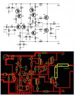
aetosa, you can't say that you have not been warned, you've chosen a project that is simply :bs:
Did it take a few seconds and then r16 heated up ? And the new one was heating up immediately ? If yes, there is already something else burned. I am wondering how you got the outputdevices with this orientation on an adequate heatsink ?
Mike
Did it take a few seconds and then r16 heated up ? And the new one was heating up immediately ? If yes, there is already something else burned. I am wondering how you got the outputdevices with this orientation on an adequate heatsink ?
Mike
aetosa i had the same problem, are you hooking Q8 and Q9 to the same heatsink?. If so that might be the problem. The circuit is shorting out because the irf530 and 9530 have a 4th pin which is connected to the heatsink. The 4th pin is the drain by the way , +33 volt and -33 volt is connected to the drain. I used two different heatsink and it solved the problem for me. Hope that help.
- Status
- This old topic is closed. If you want to reopen this topic, contact a moderator using the "Report Post" button.
- Home
- Amplifiers
- Solid State
- 30W amp ? P3A, DoGC, OPA549, P101 ?