
Hi Djk,
are you pulling the wick?
I am not interested in specs, particularly copying D.Self.
If I had the skills and equipment I would use analysis to find and eliminate imperfections.
Sound quality is paramount.
This does not invalidate my nor Lineup's enquiry.
If you have found a tweak that improves the quality of the Leach then share it.
are you pulling the wick?
I am not interested in specs, particularly copying D.Self.
If I had the skills and equipment I would use analysis to find and eliminate imperfections.
Sound quality is paramount.
This does not invalidate my nor Lineup's enquiry.
Would these differences improve the overall sound quality of amplifer?
If you have found a tweak that improves the quality of the Leach then share it.
Greg,
I am glad to see that you didn't get upset. However, I am sorry to see that you seem to have entirely missed my point. I was afraid of being to blunt, but it seems I was way too subtle.
There is no need to apologize. I never felt stupid from your comments in this or any other threads. I never even perceived myself as a target for those accusations. Actually, I don't think those who were intended targets felt stupid either, but many probably thought that you should feel stupid yourself, for making the comments. My point never was to complain, but to try telling you to stop for a few seconds and reflect upon what image of yourself you want to present to the forum, all in your own interest.
There are cultural differences. In som cultures it is more normal to brag and boast about oneself whenver getting a chance. However, in most countries (I think) it is not a good thing to do so. Actually, I have never perceived australians as having this habit. The only country where I have found this behaviour common is the US, but even then, there are very few if any americans doing so on this forum. The point is, that you probably are a competent and intelligent amp designer. I personally find the SKA both clever and interesting. However. bragging so much about it every now and then, and insinuating that almost all other designs are bad, only serves to discredit yourself and the SKA. I wouldn't be the least surprised if you scare away more potential customers than you attract, by this behaviour, but that is you own problem and your own decision. Besides, I am surprised the moderators haven't reacted yet to all the advertisement you are making. I am fairly tolerant to such marketing, even if I don't like it and find it tiring, but I can assure you there are many of our respected professional members who have zero tolerance for such marketing practices.
So, my point wasn't to complain at all. I merely tried to be helpful to you, by giving you a hint that maybe you are working very hard to discredit yourself, without realizing it. Note that I didn't explicitly point you out. However, since most people seem to have realized who I had in mind is an indication that I am not the only one seeing it this way.
AndrewT said:Hi Djk,
are you pulling the wick?
I am not interested in specs, particularly copying D.Self.
If I had the skills and equipment I would use analysis to find and eliminate imperfections.
Sound quality is paramount.
This does not invalidate my nor Lineup's enquiry.
If you have found a tweak that improves the quality of the Leach then share it.
afaik, prof. leach chose 2mA currents for each leg of the ltp as he felt this current level as optimum for gain and noise.
if you have a transistor that has higher beta than what prof leach used, this is a good place to start.
increasing ltp currents of course entails circuit adjustments as your vas will dissipate more at quiscient.
what do you think?
and greg,
please do not assume that people who praises leach and his amps have buiilt nothing but leach amps, you don't know that for sure, do you?
cheers.

I've found a few useful tips on amp design.
Excessive GNFB is no problem as long as the feedback network and amp signal path is FAST........ This means at least 150MHz input device, 100MHz voltage amp, and 30MHz drivers and output devices.
About half a milliamp on each leg of the LTP - 1mA stage current - seems about right. It's not that critical, actually. 0.25mA is on the low side, while 5mA is a bit high and drives up dissipation in the devices, which should be kept around 50mW max for greatest offset stability.
Cascodes on the LTP and the VAS give better HF response but require more lag compensation to make the amp stable by the HF pole. They don't seem to improve the sonics any, either.
CFPs look very sexy, but I find them unstable in Class AB, particularly the negative rail pair. The best sound is still the old double emitter follower.
There's a lot of comment about old topologies, 'stone age' this and that, but I have seen no evidence that done right these older, Bailey derived amps sound bad - in fact, they sound the best of all to me, and I've heard a few in past decades. After all, the straight six is still the smoothest gasoline engine - just ask BMW. The chief contributor to sonics seems to be the VAS and input stage; and a huge pitfall in amp design is poor compensation regimes.
Cheers,
Hugh
Hi John-china,
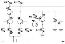
A 2BJT current source on each supply feeding a bypassed resistor for the cascode bias and tail currents is in my view preferable as it will improve PSRR and eliminate the zeners. The RC filters in the supply lines can then be removed as the PSRR will be good enough without them.
RC rail filters generally have a considerably higher impedance than the rails and can superimpose stage distortions on their impedance along with non-linear Vas input Z, which then feeds to later stages as signal.
Changing to my suggested configuration with 2 cascode BJTs per side allows the flexibility to try many different variations not permitted by the simple std arrangement, to home in on the best sound.
Cheers,
Greg
[QUOTE
A 2BJT current source on each supply feeding a bypassed resistor for the cascode bias and tail currents is in my view preferable as it will improve PSRR and eliminate the zeners. The RC filters in the supply lines can then be removed as the PSRR will be good enough without them.
[/QUOTE]
do you means that refer to my attchment jpeg?
Attachments
Hi John-china,
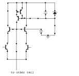
No not quite. You need to replace the resistive feed from the power supply with the CCS. The second cascode BJT is included as well and may or may not have a load R.
The zener here contributes to a very stable operating point without the noise getting through due to the NFB feedback pair. But the output Z of the CCs is orders of magnitude higher than the original R feed.
Much of the simplicity is lost though.
pic -
Cheers,
Greg
Attachments
Excessive GNFB is no problem as long as the feedback network and amp signal path is FAST........ This means at least 150MHz input device, 100MHz voltage amp, and 30MHz drivers and output devices.
exactly as prof leach proposed in his 1975 article published in the AUDIO magazine article about slew rate problems and how to vaoid them.
the japanese have been at this for a long time, that is why they come up with high Ft's power transistors for use in their amps.
that is why Mr. AKSA prefers them for his amps too.
Hi Greg, lots of options, some "simpler" ones:
losing the feedback Q and moving the zener bypass C to the ccs Q base in your circuit will be quieter - it is really "inefficient" to try to filter Zener noise with a parallel cap due to the low dynamic Rz - using RC filtered Zener V as ccs ref lets you use a much larger ccs R, total noise should be smaller than 2 Q ccs shown, if not quite as high in Zout and psrr it is still very good
with the original Leach bias adding a bootstrap resistor to each tail from the amplifier output can hugely increase effective tail impedance if the existing bias R and the added bootstrap R ratio equals the feedback network ratio - won't work all the way to DC with feedback network AC grounded but should give ~50x (1% R's) tail impedance boost over most of the audio range really cheap
I like to see trim pots in schematics like this, manual trimming of diff pair Ic balance is required with single ended outputs - may require vas degen trim for complete circuit balance
JCX,
Another method of trimming the current balance in a diff pair is to either trim the load on the single ended output (normally a current mirror, so merely alter the CM degeneration), OR trim the base bias resistor on the input (with matched LTP of course). This avoids unbalancing the gain of the LTP outputs; an advantage for distortion cancellation even if the output is in SE.
cheers,
Hugh
andy_c said:As a former student of Dr.Leach from the mid '70s to '80, I'd like to weigh in on this discussion by just posting this link
Dr. Leach doesnt sing too bad

- Status
- This old topic is closed. If you want to reopen this topic, contact a moderator using the "Report Post" button.
- Home
- Amplifiers
- Solid State
- about ccs of Leach Amp