I have just designed a crossover for subs. The PCBs have been submitted and are going through with the current lot.
The design uses a OPA4134PA quad high performance FET cascode input op amp.
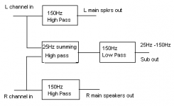
It uses 2 op amps as left and right channel sallen and key 12 dB/octave high pass filters for the main speakers.
A summing MFP low pass filter sums both channels and provides a bass boost filter (optional) similar to the bass extender to control out of band cone flapping and provide bass extension allowing a smaller stronger box for the sub. The last op amp provides a 12 dB/octave band limit for the sub upper limit and can match the filter response of the mains.
So it's one 4 op-amp chip doing stereo main out 12 dB/octave
and 12 dB/octave mono sub band limited. Gain setting is possible.
Also using my same 80 dB +/- Vs discrete regulated supplies and wallwart power option or +/-18 to 25V DC.
It's about 1 week away for the finished unit.
Cheers,
Greg
The design uses a OPA4134PA quad high performance FET cascode input op amp.
It uses 2 op amps as left and right channel sallen and key 12 dB/octave high pass filters for the main speakers.
A summing MFP low pass filter sums both channels and provides a bass boost filter (optional) similar to the bass extender to control out of band cone flapping and provide bass extension allowing a smaller stronger box for the sub. The last op amp provides a 12 dB/octave band limit for the sub upper limit and can match the filter response of the mains.
So it's one 4 op-amp chip doing stereo main out 12 dB/octave
and 12 dB/octave mono sub band limited. Gain setting is possible.
Also using my same 80 dB +/- Vs discrete regulated supplies and wallwart power option or +/-18 to 25V DC.
It's about 1 week away for the finished unit.
Cheers,
Greg
Workhorse said:Verma Saheb.....Kareena Ko kya Karizma par ghumayoge....Yaar hamein bhi sath leh chalo......
aapka swagat hai

PAR Kareena ke baad
sagarverma said:
aapka swagat hai
PAR Kareena ke baad
Chalo Aisa Karte hein ki Tum Kareena ko KariZma par le chalo, Hum piche piche Bullet Electra par Chal dete hai .....
Lets have the Fun together....
sagarverma said:hi Kanwar
yeh guru vigyaapan deta rehta hai.baddi baddi batein likhta hai.iske circuit mujhe toh avg. lagte hai par woh unhe aise batata hai jaise ki no.1 hai.
Are yaar yeh jo guru hai na, yeh har waqt shuru rehta hai kuchh karne ke liye...rahi vigyappan ki baat to ise hamare TV serials "Saas bhi Kabhi Bahu thi" mein le lena chahiye bahut naam kamayega...kya kare aadat se majboor hai bechara, par hai bahut achchaa..iske ckt good hai but luck iske sath nahi hai....Shah Rukh Khan ke jaise i am the best karta rehta hai.....yahaan bahut se log crack demag ke hai bach ke rehna re baba....
Hi Kanwar.
Sagarverma, that's a new look for you?
What're you saying about me? Huh?
I did the PCB from my head with some paper scribble. Haven't done a schema or sim yet. I'll do that maybe over the weekend. The functional blocks are well proven in multiway crossovers I've done before in a former life.
All on a 3" x 2" fully ground planed through hole plated board with teflon solder mask both sides and component overlay.
Cheers,
Greg
amplifierguru said:Hi Kanwar.
Sagarverma, that's a new look for you?
What're you saying about me? Huh?
Cheers,
Greg
Just Pulling your Strings to keep you in Control Baby
hi guru,
jus talking.nothing bad.
nice look naa
for crossover,u r using expensive chip like opa.. i guess,most of the opamps except o/p buffers will be at unity gain.so what sonic benifits to b obtained.use opa for o/p stages only.
moreover using quad inc. chances of crosstalk.mono chips good.
hi kanwar,
i have relied to your mail,u can check.
Hi Sagarverma,
Yes i am using quality OPA4134 which is 4 x OPA134 FET cascode op-amps with 8MHz UGBW ( I hope 4 letter acronyms are acceptable) and 20V/uS, under light loading. Also with quality 80 dB discrete regs and quality ground planed PCB so the potential of the design can be realised.
Sonic benefits - Well it's a quad chip so better value and better sonics from using quality chips all through.
Is that your feminine side?
Cheers,
Greg
amplifierguru said:
Is that your feminine side?
correct that::better half.
well ,i know bout that chip(so no need for those datasheet figures).nice,infact very nice.giving great service in car preamp.i have 134.will replace tl071 for o/p stages of my 24db/lr 3 way,xover(ESP) with opa.rest all r tl071(unity operation).
no doubt ,opa beats tl0 on most counts.but for unity gain,i dont think any improvents will be got.
keep on coming with your circuits.

Sagar
Hi Sagarverma,
Unity gain config is the most demanding of the input stage CMRR as the input stage is modulated at the same level as the output signal so CMRR weakness will be highest. The OPA134 series have a much better FET cascode front end and CMRR than TL0xx.
Burr-Brown however has fudged all their THD measurements by using a flawed scaling test methodology and I have taken issue with them on this and also publicly exposed this in a letter to WW in mid 1993, when Ian Hickman used it as well. It gives great THD figures but is flawed.
Cheers,
Greg
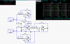
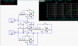
Ok here is the schematic (no values - they've yet to be set). Besides they will need to be tabled to suit different needs/applications.
So we have a 12 dB/octave Sallen and Key unity gain for each main left and right channel. Say 150Hz HP.
Then we have the two inputs summed and filtered by an inverting, summing 12 dB/octave 150Hz LP filter which then feeds a 12 dB/octave (say) 15Hz HP subsonic filter.
The sub output will be inverted so speaker phase can be reversed.
The filters can be set as Bessel, L-R, Butterworth (or Q=2 for the subsonic for bass extension or smaller box)., just by adjusting R values around standard C's. R1 can change sub gain independant of filter response.
Cheers,
Greg
Attachments
Hi Avwerk,
A notch filter as well, with variable width and frequency? Where?
I've no space, or chip power left to do that (could only fit one quad). It's another little 2" x 3" board just like the Bass Extender with the discrete 80 dB regs taking half the space. Also it puts only one op-amp into each main L/R channel, and 2 (one inverting) in the bass channel, so is minimalist.
Here's typical main out for L/R.
Cheers,
Greg
Attachments
- Status
- This old topic is closed. If you want to reopen this topic, contact a moderator using the "Report Post" button.
- Home
- Amplifiers
- Solid State
- New Sub XO