Hi, all
That circuit attached I found in a "old" Fairchild applications book.
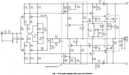
(Application Note 336 - July 1977: 75 W Hi Hi Audio Amplifier with low transient intermodulation
distortion)
A PDF of the whole article ist available if you're interested (includes component and board layout - 392 KB).
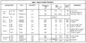
As a bloody amateur I would be very interested in comments, and in your suggestions for replacments for the FT transistor types, as well.
Peter
That circuit attached I found in a "old" Fairchild applications book.
(Application Note 336 - July 1977: 75 W Hi Hi Audio Amplifier with low transient intermodulation
distortion)
A PDF of the whole article ist available if you're interested (includes component and board layout - 392 KB).
As a bloody amateur I would be very interested in comments, and in your suggestions for replacments for the FT transistor types, as well.
Peter
Attachments
widowmaker said:Double differential input stage (pnp, npn), an ordinary AB power stage...
With all these components is possible to make almost (except output transistors) two channels and they are sounds better than this one")
Any schematic please? No FET inputs? What do I know?
Fairchild Amplifier
For what its worth
The Fairchild application was the basis of several amplifiers mentioned above but probably the most interesting was the Audionics CC02 ampfilier. Robert Sickler, an Audionics technician modified the Fairchild resulting in a very good amplifier that played music. One of my favourites and still holding its own in today's Class AB company. A detailed story and circuit diagram of the CC02 can be found on Lynn Olsen's website: http://www.nutshellhifi.com/
If you can post the pdf of the Fairchild application note it would be much appreciated.
Regards Ejam
I found this article and schematics of the Audionics CC02 ampfilier
at the above website.
Wasnt so easy to find
so
A Tribute to Bob Sickler
at the above website.
Wasnt so easy to find
so
A Tribute to Bob Sickler
Re: Fairchild Amplifier
CC2 is a pretty good amp for the late '70s, though I prefer the GAS Grandson (I own both). Still has a following especially in bridged mono mode, they show up on eBay from time to time for about US$150. A real PITA to work on though due to the packaging, lack of PCB silkscreen, and the output stage bias thermal tracking is kinda loose. Try reconfiguring for inverting input, clarity is much improved but DC coupling for this one may not be your cuppa. There was more than one power transformer used, the one I has two isolated secondary windings so can be wired with two bridge rectifiers.
Ejam said:Audionics CC02 ampfilier. Robert Sickler, an Audionics technician modified the Fairchild resulting in a very good amplifier that played music. One of my favourites and still holding its own in today's Class AB company.
CC2 is a pretty good amp for the late '70s, though I prefer the GAS Grandson (I own both). Still has a following especially in bridged mono mode, they show up on eBay from time to time for about US$150. A real PITA to work on though due to the packaging, lack of PCB silkscreen, and the output stage bias thermal tracking is kinda loose. Try reconfiguring for inverting input, clarity is much improved but DC coupling for this one may not be your cuppa. There was more than one power transformer used, the one I has two isolated secondary windings so can be wired with two bridge rectifiers.
Hi blink,
You're posted schema is a rather acadaemic design based on a non-event (TIM). It has poor PSRR due to the poor decoupling of tail currents and higher distortion than it could have ( the unnecessary 22K's as Vas collector load) and it is suseptable to hum pickup due to the high impedance of the input filter.
Rather than build something old, based on a false premise, why not build something new and fast using today's technology. Simple and efficient and patent pending.
http://members.dodo.com.au/~gregball/guru_004.htm
Cheers,
Greg
amplifierguru said:Hi blink,
You're posted schema is a rather acadaemic design based on a non-event (TIM). It has poor PSRR due to the poor decoupling of tail currents and higher distortion than it could have ( the unnecessary 22K's as Vas collector load) and it is suseptable to hum pickup due to the high impedance of the input filter.
translated means....
A couple of minor mods and you'll have a half decent amp.
regards
Elso Kwak said:
Any schematic please? No FET inputs? What do I know?
I have my own project, if you want, I'll send you documentation...
But... why "no FETs input" ?
- Status
- This old topic is closed. If you want to reopen this topic, contact a moderator using the "Report Post" button.
- Home
- Amplifiers
- Solid State
- Fairchild amp application