rowemeister said:The caps are for stopping potential dc entering the amps input stage. As standard most devices use 2 electrolytic caps in series and reverse polarity to each other making it the same as a non polar.
Brent
ah, thanks. i was just thinking of a cdp all of a sudden. i don't think my cdp outputs any dc either.
auriches said:should small (0.1uF) ceramic caps be replaced/bypassed if they are the only input/output caps used?
The signal won't likely be going through any cap so small. Are these caps in parallel to the signal? If so, they're less important.
Simon
SimontY said:
The signal won't likely be going through any cap so small. Are these caps in parallel to the signal? If so, they're less important.
Simon
ah, i'm looking at the schematic and at the cd input there are only these small parallel ceramic caps. where are these electrolytics we're talking about? the signal path looks pretty clear.
Hi Brent,
you've done quite a few mods to your amp. which mods made the most difference? i would like to do something similar with mine but the cost of those black gates are very discouraging.
if, for example, i replaced the standard elna's with cerefines would it make much difference?
also, for the large power supply caps, how did you secure the cap in the space?
thanks
Hi Brent,
thanks for the suggestion.
i was thinking of replacing the power caps but i can't find anything that will fit exactly (with the same size as the originals). do you have a pic of yours?
i was thinking of tweeking the bias current as you did. how did that affect the sound?
would cerafines all round be a good idea/improvement? they are, afterall, elna and there's plenty of the standard ones already onboard the amp.
Here are the large images from inside 2 of my KI amps L/R AMP Centre AMP . Use the centre channel amp to start off with for you mods upgrades. The cerefines should be ok, not as good as the BG but still good. Try them and see how you like the overall improvement.
Be very careful with bias current, go silly and you will blow up your outputs. First of all from cold monitor both channels on the bias as per the service manuals instructions. If you are going to adjust the bias a tad i advise fitting precision pots so you can adjust spot on. Dont take the standard mV much above 20mV either on those heatsinks, also the standard idle setup says 6 mins for 14mV well I would work to 10mins minimum for 20mV.
You get a slightly smoother and more dynamic sound from this, just another little tweak that adds up.
Brent
SimontY said:
The signal won't likely be going through any cap so small. Are these caps in parallel to the signal? If so, they're less important.
Simon
does 3.3 uF too small cap value for all the signal bandwith
I am seeing that at the output stages of cd players In decoupling cap Is 100 uF elektrolyt and the output decoupling cap Is 47 uF elektrolyt
My player has that values and I don't know exactly with what value to replace
samoloko said:
does 3.3 uF too small cap value for all the signal bandwith
I am seeing that at the output stages of cd players In decoupling cap Is 100 uF elektrolyt and the output decoupling cap Is 47 uF elektrolyt
My player has that values and I don't know exactly with what value to replace
They may use such values but two 10uF electrolytics would be fine (wired in series so 5uF, right?). They're playing it safe and electrolytics are cheap and small.
Simon
auriches said:doesn't the manual say >5min for 10mV?
btw, how do i work out the power output with this current?
thanks
The 66 manual specifies >6min for 14mV. Strange that as its the same circuit.
The calculation is mV/R = mA. R being the output resistor of 2x 0.1 ohm
So for you it is 14mV/0.2 = 70mA
and after a tweak 20mV/0.2 = 100mA
25mV/0.2 = 125mA
30mV/0.2 = 150mA etc etc
Brent
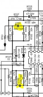
Wow can i just say a big thanks to this forum. I've had a Marantz PM 66 Ki that hasn't been working for about 4 years. I wanted to get this beast working again so decided to search the web for common problems of this amp and came accross this thread where user "rowemeister" commented
So i hastily had a search inside my amp and low and behold a 47ohm resistor at R802 had blown, quick trip to maplins and 15 minutes soldering later, she's singing again
To say i'm chuffed to bits is an understatement")
Just a quick question, i'm quite new to this (only found out yesterday what the different colours on the resistor meant!!) and couldn't match the resistor exactly at maplins.
The one in the amp is Yellow, Purple, Black, Brown and then White (Can't find a reference for a resitor with white at the end ??)
The one i got is Yellow, Purple, Black, Gold and then Brown which = 47ohm +/- 1 % tolerance.
Do you think it will be ok or should i try and hunt down for the exact colour match ?
Either the output as blown or a 47ohm resistor in the psu has gone open circuit.
The reference for this resistor(s) is R801 or R803. These go with age as they run warm.
So i hastily had a search inside my amp and low and behold a 47ohm resistor at R802 had blown, quick trip to maplins and 15 minutes soldering later, she's singing again
To say i'm chuffed to bits is an understatement
Just a quick question, i'm quite new to this (only found out yesterday what the different colours on the resistor meant!!) and couldn't match the resistor exactly at maplins.
The one in the amp is Yellow, Purple, Black, Brown and then White (Can't find a reference for a resitor with white at the end ??)
The one i got is Yellow, Purple, Black, Gold and then Brown which = 47ohm +/- 1 % tolerance.
Do you think it will be ok or should i try and hunt down for the exact colour match ?
- Status
- This old topic is closed. If you want to reopen this topic, contact a moderator using the "Report Post" button.
- Home
- Amplifiers
- Solid State
- Marantz PM66 KI tweeks