i didn`t asked this becose i don`t know how to read datasheet!
In datasheets irf540 and irf9540 doesn`t have same bias voltages and they`re used as a complementary pair.
In some schematics I read that bias voltage should be 2.1V,(for
36V power supply).
I tried it and at the gate voltage 2.1V, the drain current is MUCH less then 500mA as they say it should be.
sorry for the bad english.
bogdan_borko said:In datasheets irf540 and irf9540 doesn`t have same bias voltages and they`re used as a complementary pair.
Do a thread search and you can read a lot on IRFs here on DIYaudio.
Many of them are not complementary pairs, not even the 240 and 9240, as Ilimzn from Croatia took the trouble of explaining several times already.
That is for a major part the trouble with vertical MOSFETs and why the attention has gone to lateral types for so long. Lateral MOSFETs do come/came in decent complementary pairs.
Besides the effect of temperature difference, transconductance between 2 MOSFETs can vary just like Hfe can for 2 BJTs.
Datasheets are guidelines for designing a circuit, getting the right Vgs for a required bias is done by selection or by using a Vgs multiplier and adjusting. Some find the right VGs resistor value with a trimpot and then replace it with a fixed value resistor.
On a hybrid tube/mosfet amplifier i constructed i tried separate Vgs multipliers to compensate for the difference between both IRF output device types.
On advice of Ilimzn i am now trying the 240 and 9140 as complementaries on a pushpull amplifier, as he sees them as a better match for complementarries then the supposed ones.
Till now i saw vertical fets as only good for single ended use.
bogdan_borko said:I didn`t asked this becose i don`t know how to read datasheet!
In datasheets irf540 and irf9540 doesn`t have same bias voltages and they`re used as a complementary pair.
They are used as a complementary pair only by those who do not know how to read datasheets, more precisely, who do not understand wht is written in tham and what parameters are important for a given application and why.
Looking at the datasheets makes it obviously clear to anyone who has any idea about what complementary means, that these are not complementary. And guess what, they really are not!
In some schematics I read that bias voltage should be 2.1V,(for
36V power supply) I tried it and at the gate voltage 2.1V, the drain current is MUCH less then 500mA as they say it should be.
And why is this a mystery if the datasheet clearly says 4V for 1A at 25 deg C? This should make it about 3.3V for 500mA for the IRF540. The IRF9540 has a higher Vgs for the same current and same temperature because it has about half the transconductance of the IRF540.
If you dont wanna help, dont vaste your time being ironic.
it`s stupid!
No, it's not - it is a way of politely telling you that you are asking the wrong question. The bias voltage of a MOSFET should be irrelevant in any amplifier, except maybe when you are using the MOSFET as a Vgs multiplier to sense the temperature and compensate the bias CURRENT. A design should provide a means of adjusting the bias CURRENT, accounting for a relatively wide variation in bias voltages found in MOSFETs, and also, there should be a means to compensate for changing temperature. Without this, unless heavily degenerated, vertical MOSFETs WILL go into thermal runaway. In other words, you should really not be asking about a MOSFET bias voltage since this is not the relevant parameter you want to target - it will vary as much as +-50% depending on sample and temperature.
In your case, your Vbe multiplier will overcompensate for temperature, quite badly actually. It would overcompensate even if there were no source resistors (0.22). You need to 'degenerate' the BD139, by putting a small resistor in it's emitter. It will be a matter of experiment to see what it will have to be. Alternatively, you may want to use a Vgs multiplier (replace BD139 with a small MOSFET like the IRF510 or 610). Finally, NEVER EVER implement a bias regulation potentiometer like in your diagram. Should the pot viper have bad contact (which is not uncommon on standard pots, especially while it's being adjusted), you get maximum bias voltage -> short circuit from + to - Vdd through both MOSFETs. Use a fixed resistor from C/D to B/G, and a trim pot from B/G to E/S. Keep in mind the resitor to pot resistance ratio will be different for Vbe and Vgs multipliers because Vbe~~0.6V, and Vgs~~3V.
jacco vermeulen said:On advice of Ilimzn i am now trying the 240 and 9140 as complementaries on a pushpull amplifier, as he sees them as a better match for complementarries then the supposed ones.
Make sure none of your IRFPs are the N suffix ones (these are quite different). And I do look forward to your impressions!
any BJT or MOSFET, the input vb/vg may not accurately determine the Ic/Is as each one has slight different curve.
Your schematics cannot be used, becasue MOSFET needs 4~10V Vgs to drive it. If you dont' change the connection, then diver stage needs higher voltage than output stage becasue of that.
Your schematics cannot be used, becasue MOSFET needs 4~10V Vgs to drive it. If you dont' change the connection, then diver stage needs higher voltage than output stage becasue of that.
lastguy said:Any BJT or MOSFET, the input vb/vg may not accurately determine the Ic/Is as each one has slight different curve.
In the case of a BJT, the relationship is exponential and a change in milivolts can result in an Ic change in amperes - AND Vbe is also temperature dependant at a constant Ic, so at a constant Vbe, Ic will be HEAVILY thermaly dependant (inside normal operating temperature ranges, 1:100 current variations are not at all uncommon). This is wht you NEVER design for constant Vbe unless you are trying to design some sort of thermal sensor.
MOSFETs have a polinomial relationship, which is not as steep a curve as an exponential. Their gm (change of Id vs change of Vgs) is much lower than BJTs, and the temperature coefficient of Id at constant Vgs varies from positive to negative - with the point where it becomes negative, dependant on the technology used. For lateral MOSFETs (also known as 'audio MOSFETs') this is usually on the order of 100mA or so, because this will be the order of magnitude of the idle current, extra temperature compensation is usually not required. With vertical MOSFETs (and similar technologies), the point where the temperature coefficient becomes zero is usually on the order of the maximum MOSFET current, so usually 5-10A, so additional temperature stabilisation is necessary.
Vbe on BJTs and Vgs on MOSFETs at a given current also exhibit a different temperature coefficient in mV/deg C, which must be taken into account - especially when a BJT is used to temperature compensate a MOSFET.
With all that, the actual Vbe or Vds for a given current varies substantially between instances of the same part. Because MOSFETs have lower gm, the variations are not as critical as with BJTs but they can still be +-30% or more, for vertical MOSFETs.
Your schematics cannot be used, becasue MOSFET needs 4~10V Vgs to drive it. If you dont' change the connection, then diver stage needs higher voltage than output stage becasue of that. [/B]
The driver is not shown on the schematics, so it is quite possible it will be capable of providing output higher than the MOSFET buffer rails, threfore the connection could be used. The coupling caps will provide 'bootstrap' action over and under the rail voltages if the input can swing to the rails. Still, Vgs of the MOSFET must be limited to less than +-20V WRT source or the part will be destroyed. Zener clamps are most commonly used for this. Keep in mind that Vgs can become higehr than maximum if the output is shorted!
HI ILIMZN!
Thanks a LOT for precise advices of yours! I think that you
didnt undertand me very well...it`s my fault!
I can`t find 240/9140 pair here in Serbia so I`ll have to
realase this with 540/9540...(this would be much easyer on
Serbian/Croatian...wathever...I hope that we will
understand each other anyway).
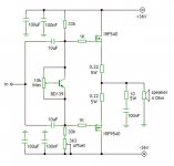
I made some changes and it looks like this now.
Still got some questions for you:
1. Can this diode (connected to BD139 emiter) do the
temperature compensation ? I`ve seen this in some
schematics. (BD139 is on the heatsink with mosfets, and
emiter diode is not).
2. Should I remove the diode and leave just the emiter
resistor as you suggestet?
3.I made this circuit and it works fine,except one imortant
thing ! - Bias current is unstable, depends very much of
temperature! BD139 is on the heatsink with the mosfets.Is
it right? What should I do?
4.What do you think about mosfet-gate resistors? Is 1K ok,
or it should be smaller value?
PLEASE send me some schematics for 540/9540 Power follower
you`ve made!
I HOPE YOU`LL UNDERSTAND WATH I`M ASKING...
THANKS IN ADVANCE!
Thanks a LOT for precise advices of yours! I think that you
didnt undertand me very well...it`s my fault!
I can`t find 240/9140 pair here in Serbia so I`ll have to
realase this with 540/9540...(this would be much easyer on
Serbian/Croatian...wathever...I hope that we will
understand each other anyway).
I made some changes and it looks like this now.
Still got some questions for you:
1. Can this diode (connected to BD139 emiter) do the
temperature compensation ? I`ve seen this in some
schematics. (BD139 is on the heatsink with mosfets, and
emiter diode is not).
2. Should I remove the diode and leave just the emiter
resistor as you suggestet?
3.I made this circuit and it works fine,except one imortant
thing ! - Bias current is unstable, depends very much of
temperature! BD139 is on the heatsink with the mosfets.Is
it right? What should I do?
4.What do you think about mosfet-gate resistors? Is 1K ok,
or it should be smaller value?
PLEASE send me some schematics for 540/9540 Power follower
you`ve made!
I HOPE YOU`LL UNDERSTAND WATH I`M ASKING...
THANKS IN ADVANCE!
Attachments
Hi Bogdan,
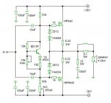
Split the 33K feed resistor into two 15Ks from both rails and run a 47uF electro from the mid point of each string to the amp output.
This double bootstrap will ensure near constant current through the driver stage and give you far more swing at the gate, allowing you to output within 1V of the rails.
This extra efficiency is extremely important with mosfets, which have poor use of the rail voltage.
Cheers,
Hugh
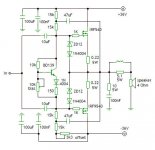
Yes, Bogdan,
Exactly like that!!
The great advantage of this double bootstrap concept is driving the gates ABOVE the rails. This is a huge benefit when using Mosfets. A secondary benefit is that the input impedance to your buffer is greatly increased, from around 12K to something approaching 50K (guestimate only) since the impedance of the bootstrap is very high. A third benefit is that the effectiveness of the bootstraps starts to fall off around 300KHz, which is useful to prevent RF frying your tweeters.
I'd leave the BD139 exactly as it is; you may need to place only the emitter diode on the heatsink, not the transistor, so that tempco is not too steep.
I'd go for 0.33R source resistors. As you go beyond 0.22R the tempco issues with mosfets very rapidly improve.
You will have gain droop as the amplitude increases because there is no global feedback loop to correct losses in the source resistors. But at domestic power settings, I doubt this would make much difference to the sonics.
Your technical English is just fine. Don't agonise over it; it will slow you down. English has a lot of redundancy in it, so it's easy to pick out the meaning regardless of lexicon or syntax. This is particularly useful in technical matters, where English excels.
Cheers,
Hugh
AKSA has given you some good advice. I would however use larger capacitance for bootstrapping, perhaps even 470uF.
Increased source resistors will reduce temperature coefficient a lot which is a godo thing, and equalize the gm of the MOSFETs, again good, but it will also decrease effective gm, which in turn increases output resistance. This may be a problem (depends on several factors, not the least of which are your speakers).
I have tried a lot of output variations with single MOSFET pairs, and have come to the conclusion that if you have a single pair (so current sharing is not an issue), the ebst results are when you have no source resistors - BUT in order for this to be so, you have to chose your MOSFETs carefully for good complementarity, and also pay a lot of attention to temperature compensation. The best way to do this I have found to be a Vgs multiplier - the equivalent of your BD139 circuit (but without diode and emitter resistor) using a MOSFET. Even a 'large' MOSFET like the 540 will do fine in this application, and it heps if D-S is bridged by a cap of about 10nf (the idea is to have at least 5x the Cgs of the MOSFET).
Regarding the temperature coefficient - how is the bias current unstable? Does it rise with temperature or fall?
When you use a 'straight' Vbe multiplier (no diode or emitter resistor), the Vbe multiplier will overcompensate and reduce the bias current too much as temperature rises. You can try using just the resistor, start al low values (56 ohms or so) and increase until you get slightly negative temperature coefficient with rising temperature. Because the compensation curves are slightly different for MOS and BJT, you may see a situation where the bias first rises then falls. You can use a hair dryer or hot air gun to test this by heating up the ehatsink! BD139 must be on the heatsink, of course.
Also, you may want to try IRF640 and IRF9540 as complementary pairs - they are not as good as IRFP240/9140 at complementarity, but better than 540/9540, see Vgs vs Id curves I have attached in the pic below!
Attachments
- Status
- This old topic is closed. If you want to reopen this topic, contact a moderator using the "Report Post" button.
- Home
- Amplifiers
- Solid State
- IRF540/IRF9540 bias