Hello all!.. Just wanted to see if anyone have used www.vicr.com modules in their amp?.. and if so, what experiences was there?...
I'm using 4,100watt modules i found at work..
28volt (dual mono).. I'm posting a couple of pic's too so you can look at my amp, ..
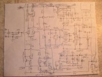
Before you start critisising the schematic i just want to say that it's just a fast thing i connected instead of my old 6n1p u-stage, i have a new design I'm gong to use later on with much lower thd, with that said i'm still very pleased with the sound..
http://deeper.mine.nu/amp/ampf.jpg
http://deeper.mine.nu/amp/kontakt5.jpg
http://deeper.mine.nu/amp/schemaseha.gif
http://deeper.mine.nu/amp/levels.jpg
http://deeper.mine.nu/amp/boarde.JPG
http://deeper.mine.nu/amp/kontakt8.jpg
I'm using 4,100watt modules i found at work..
28volt (dual mono).. I'm posting a couple of pic's too so you can look at my amp, ..
Before you start critisising the schematic i just want to say that it's just a fast thing i connected instead of my old 6n1p u-stage, i have a new design I'm gong to use later on with much lower thd, with that said i'm still very pleased with the sound..
http://deeper.mine.nu/amp/ampf.jpg
http://deeper.mine.nu/amp/kontakt5.jpg
http://deeper.mine.nu/amp/schemaseha.gif
http://deeper.mine.nu/amp/levels.jpg
http://deeper.mine.nu/amp/boarde.JPG
http://deeper.mine.nu/amp/kontakt8.jpg
I like the compact layout design. Did you make your own pcb's? The only thing I see is the HS fins might need to be open on the bottom and top to assist convection. Of coarse, this depends on how much heat needs to dissapate.
How good are you at soldering SMD's? This may be an approach as space is limited here. I just made a SMD(well mostly) BJT circuit that output about 35WRMS into 2 Ohms. May be higher with a larger power transformer, it clips at 12V but about 16V on 4 Ohms, or like 30WRMS. Transformer is cheap radio shack 12.6V-0V-12.6V @2A. I don't suppose that is too bad for efficiency.
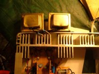
Yours is alot prettier than mine...I call this one the getto style, or low budget enclosure. It sounds great though. I just completed channel 2 of 4....
How good are you at soldering SMD's? This may be an approach as space is limited here. I just made a SMD(well mostly) BJT circuit that output about 35WRMS into 2 Ohms. May be higher with a larger power transformer, it clips at 12V but about 16V on 4 Ohms, or like 30WRMS. Transformer is cheap radio shack 12.6V-0V-12.6V @2A. I don't suppose that is too bad for efficiency.
Yours is alot prettier than mine...I call this one the getto style, or low budget enclosure. It sounds great though. I just completed channel 2 of 4....
Attachments
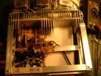
Made the pcb in eaglepcb,, yeah I thought of the fins, but it seems to be ok cooling, it does'nt get very hot.. I could do an smd board hmm, i guess i'm pretty good soldering smd's considering that's what I do for a living :-D.. Hmm so far, i cant hear the vicors except maybe that i think the bass sounds good, and i enjoy the dual mono design.. I've set the current now on 0.25 amperes, pretty low, i might want to up that a bit in the future.. space will be better in the next design if i put the boards on the coolingfins instead instead of having two boards like it's now.. I played around with CMRR in the simulator yesterday, it says 60000, i read somewhere that 30000is 90dB.. and with a current mirror on the input stage it says 300000, or 110dB???? ,, NOW does that affect the sound much?? i guess i'll try current mirror on the next lab board.. just to see if..
also i want to replace the output transistors to irfp240/irfp9140 that was the best performing pair in the simulator in that series of transistors, couldnt find audio fet's
also i want to replace the output transistors to irfp240/irfp9140 that was the best performing pair in the simulator in that series of transistors, couldnt find audio fet's
CBS240 said:I like the compact layout design. Did you make your own pcb's? The only thing I see is the HS fins might need to be open on the bottom and top to assist convection. Of coarse, this depends on how much heat needs to dissapate.
How good are you at soldering SMD's? This may be an approach as space is limited here. I just made a SMD(well mostly) BJT circuit that output about 35WRMS into 2 Ohms. May be higher with a larger power transformer, it clips at 12V but about 16V on 4 Ohms, or like 30WRMS. Transformer is cheap radio shack 12.6V-0V-12.6V @2A. I don't suppose that is too bad for efficiency.
Yours is alot prettier than mine...I call this one the getto style, or low budget enclosure. It sounds great though. I just completed channel 2 of 4....
This is the new cr ap i'm working on..
http://deeper.mine.nu/amp/schemaseha2.gif
what about the dual feedback i have? shoud i keep it?
i'm thinking of putting a pot in so i regulate the ratio of "local" and global feedback..
also I want to test currentmirror in real life... works fine in simulator..
http://deeper.mine.nu/amp/schemaseha2.gif
what about the dual feedback i have? shoud i keep it?
i'm thinking of putting a pot in so i regulate the ratio of "local" and global feedback..
also I want to test currentmirror in real life... works fine in simulator..
This project is for my home use and therefore, I don't much care what it looks like as long as it is sturdy. The sound is much more important to me. I can pretty it up later. As for the current mirror, it will increase the sensitivity of the differential. I used the mirrored diff. with a feedback CCS, and one loading the VAS.
Using daughter boards with SMD's allows you to cram a lot of stuff inside a small space and if mounted right makes strong construction. It also allows you to test each board in a protoboarded circuit to make sure it works. Constructing IC's with discrete components. I think the general smallness keeps less parts of the circuit hanging out like a flag for RF agitation, requiring compensation that may affect the audio. If your resistor dimensions are 1.5mm X 1mm X 0.5mm, they don't take much space. In this circuit there is only 6 resistors that are not SM. Just don't try to construct a SMD circuit when you have a cold....
 Sneeze and it's gone.

I noticed a 600Khz oscillation that occurred when the input pot(logarithmic) was turned about 75%. It went away above and below that setting, so I placed a 150pf cap from the wiper to ground and it was gone. Oddly enough any capacitive feedback compensation caused instability, but works great without, even when driving a 4way 100Wrms load....only to about 30Wrms though.
I believe if your going to diy, building a kit someone else designed is not completely diy. Scratch and sound theory is a good place to start sometimes in order to really understand the circuit and why it works. Then comes construction from scratch. This circut works really well but is quite sensitive to poor construction. I think it would fit inside your little box though….unless of course you have an undying love with FETs.
Using daughter boards with SMD's allows you to cram a lot of stuff inside a small space and if mounted right makes strong construction. It also allows you to test each board in a protoboarded circuit to make sure it works. Constructing IC's with discrete components.
I think the general smallness keeps less parts of the circuit hanging out like a flag for RF agitation, requiring compensation that may affect the audio. If your resistor dimensions are 1.5mm X 1mm X 0.5mm, they don't take much space. In this circuit there is only 6 resistors that are not SM. Just don't try to construct a SMD circuit when you have a cold.... Sneeze and it's gone. I noticed a 600Khz oscillation that occurred when the input pot(logarithmic) was turned about 75%. It went away above and below that setting, so I placed a 150pf cap from the wiper to ground and it was gone. Oddly enough any capacitive feedback compensation caused instability,
but works great without, even when driving a 4way 100Wrms load....only to about 30Wrms though.I believe if your going to diy, building a kit someone else designed is not completely diy. Scratch and sound theory is a good place to start sometimes in order to really understand the circuit and why it works. Then comes construction from scratch.
This circut works really well but is quite sensitive to poor construction. I think it would fit inside your little box though….unless of course you have an undying love with FETs.Attachments
Just don't try to construct a SMD circuit when you have a cold.... Sneeze and it's gone.
Good point there good point hehehe..
I noticed a 600Khz oscillation that occurred when the input pot(logarithmic) was turned about 75%.
i freakin hate oscillation, it used to blow up my previous amps/speakers before I sort of learned how to get rid of it..
It went away above and below that setting, so I placed a 150pf cap from the wiper to ground and it was gone. Oddly enough any capacitive feedback compensation caused instability
Yeah, that's the way it worked for me too.. i noticed that..
resistors on the currentmirror causes instability too I noticed..
like too small gate resistors on fets, that's like begging for trouble..
I believe if your going to diy, building a kit someone else designed is not completely diy.
I my eyes, many of these designs are VERY much alike... i'm trying to look at yamaha ax1 a bit, hav'nt heard it but design looks interresting to me :-D I like to use a sort of ready design and combine with another.. I like the u-stage tube hybrid with fetoutputstage for example.. or the smala amp, that combination of classA and D is weird :-D in a positive way..
Scratch and sound theory is a good place to start sometimes in order to really understand the circuit and why it works.
Damn i like to learn stuff, but i'm a bit lazy..I like to think that i've got a good(ish) overall sense of electronics, I used to blow up bc547's before I was school age.. but i lack big knowlege of for example how fets are made inside, i'd like to study that some day, i did download some pdf's on that area
I think it would fit inside your little box though….unless of course you have an undying love with FETs.
You guessed it right hehe!! I've got a big love for FETs.
but bipolar's are nice too i guess, i 've seen them used in very expensive amps so.. i dont know which ones are better as output stage in follower config..
I'd like to cram in like SIX channels in this box some day..
Sorry for trashing up your schematic but i was wondering about how theese things would turn out??
Link to schematics..
Sneeze and it's gone. Good point there good point hehehe..
I noticed a 600Khz oscillation that occurred when the input pot(logarithmic) was turned about 75%.
i freakin hate oscillation, it used to blow up my previous amps/speakers before I sort of learned how to get rid of it..
It went away above and below that setting, so I placed a 150pf cap from the wiper to ground and it was gone. Oddly enough any capacitive feedback compensation caused instability
Yeah, that's the way it worked for me too.. i noticed that..
resistors on the currentmirror causes instability too I noticed..
like too small gate resistors on fets, that's like begging for trouble..
I believe if your going to diy, building a kit someone else designed is not completely diy.
I my eyes, many of these designs are VERY much alike... i'm trying to look at yamaha ax1 a bit, hav'nt heard it but design looks interresting to me :-D I like to use a sort of ready design and combine with another.. I like the u-stage tube hybrid with fetoutputstage for example.. or the smala amp, that combination of classA and D is weird :-D in a positive way..
Scratch and sound theory is a good place to start sometimes in order to really understand the circuit and why it works.
Damn i like to learn stuff, but i'm a bit lazy..I like to think that i've got a good(ish) overall sense of electronics, I used to blow up bc547's before I was school age.. but i lack big knowlege of for example how fets are made inside, i'd like to study that some day, i did download some pdf's on that area
I think it would fit inside your little box though….unless of course you have an undying love with FETs.
You guessed it right hehe!! I've got a big love for FETs.
but bipolar's are nice too i guess, i 've seen them used in very expensive amps so.. i dont know which ones are better as output stage in follower config..
I'd like to cram in like SIX channels in this box some day..
Sorry for trashing up your schematic but i was wondering about how theese things would turn out??
Link to schematics..
nikwal said:Sorry for trashing up your schematic but i was wondering about how theese things would turn out??
Link to schematics..
Some of this changes compleatly the operation and some I have tried like the miller feedback cap. Any type of miller compensation or feedback seemed to make the circuit unstable. I'm guessing this may have someting to do with the low C-cb of the KST5087, about 2pF at 25V.
The base of the first transistor must have DC bias. This bias came from GND through 22K to the transistor. The voltage on the emitter of each input transistor is -0.6V. If the beta of BC846C is like 400, then it still needs around 8uA DC to conduct 3mA. Since capacitors don't conduct DC, it won't work. Also you want the input referenced directly to GND or you will get all kinds of craziness.
I think your arrow is pointing at the bypassed non polar electrolitic? Electrolitic caps can generate noise. Something about them having inductance because of being rolled up in a coil.

The 28 Ohm emitter resisors in the current mirror are there for degeneration in return for loosing some gain, although they could be more like 15 Ohms. Since no device is exactly the same, this makes the % difference of the "Re" inside the transistors not as large. Trying to excactly match SMD's can be a pain in the rump. I didn't try to use the source for the mirror without an emiter resistor but keep the one in the mirror side, so I'm not sure how that would work out. I was under the impression that you need to have better matching devices to get the mirror to work right.
Increasing the gain, neg. feedback resistor, would require an adjustment of the 1K 20turn pot to zero the output but the curcuit should still work. I need just enough gain to be able to drive the amp into clipping with my laptop. Anymore is just inviting more noise for no extra improvement.
Just wanted to keep you updated of what I'm trying to do.. i'll report later with results of how crappy it works in real life.. hehe..
http://deeper.mine.nu/amp/current2.gif simulated results looks promising though.. 0.004%Thd@10khz and 0.008%@20khz simulated.
http://deeper.mine.nu/amp/current2.gif simulated results looks promising though.. 0.004%Thd@10khz and 0.008%@20khz simulated.
If anyone should happen to accidentally run by this my old thread, i'm sorry my old server is dead.. i always try to keep my (kind of bullshitting) homepage http://amp.webhop.biz up to date.. with the exeption from this http://hem.bredband.net/nikwal1/amp.gif schematic.. me experimenting with this circuit.. i'm still enjoying the amplifiers sound too :-D sounds pretty ok i my ears..
simulated 0.001%,97dBsinad @ 3khz.. and 0.002%,95dBsinad@15khz
simulated 0.001%,97dBsinad @ 3khz.. and 0.002%,95dBsinad@15khz
- Status
- This old topic is closed. If you want to reopen this topic, contact a moderator using the "Report Post" button.
- Home
- Amplifiers
- Solid State
- Vicor power modules... (+a few pictures of my new amp)