Hi everyone,
Apart from class-D , the efficiency in Linear amplifiers could be obtained by converting a Class-AB amp into Class-H amp...
I mean to say in simple words "The Rail Switcher Amp" benefits from the elimination of wasted heat incase of class-AB , by splitting the power rails into 2 or 3 TIERS, and choosing the appropriate Rail according to the Voltage Swing at output.....So that the output transistor has less VCE across it to do the job with less wastage...
I have seen many pro-amp manufacturers Quote that Class-H reduces the current consumption from as much as 30% in comparision to same wattage amp in Class-AB, meanwhile, it also states that the heatsinking requirements are much less than class-AB amp.....
But their are many challenges that must be met in order to overcome various obstacles such as Switching noise, Spikes, Seamless Transition from one Tier to another and so on....
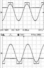
Below are the switching waveforms from a pro-amp in Class-H
regards,
K a n w a r
Apart from class-D , the efficiency in Linear amplifiers could be obtained by converting a Class-AB amp into Class-H amp...
I mean to say in simple words "The Rail Switcher Amp" benefits from the elimination of wasted heat incase of class-AB , by splitting the power rails into 2 or 3 TIERS, and choosing the appropriate Rail according to the Voltage Swing at output.....So that the output transistor has less VCE across it to do the job with less wastage...
I have seen many pro-amp manufacturers Quote that Class-H reduces the current consumption from as much as 30% in comparision to same wattage amp in Class-AB, meanwhile, it also states that the heatsinking requirements are much less than class-AB amp.....
But their are many challenges that must be met in order to overcome various obstacles such as Switching noise, Spikes, Seamless Transition from one Tier to another and so on....
Below are the switching waveforms from a pro-amp in Class-H
regards,
K a n w a r
Attachments
Hi Kanwar,
Yes Class H may save some power /dissipation but at the price of complexity. The other aspect of these switching supplies is that the artefacts can get into the amp residual and degrade image/detail/timbre... PSRR in many stages falls away at HF.
You like a challenge... I'm a simple person (PC) and like simple sweet and detailed R2R Class AB. I'm not that desperate for power to go there.
Cheers,
Greg
Hi GreG,
Yes you are right but, Class-H isn't meant for Studio or Hi-END HIFI, but its meant for PA, all these pro-amp guys[except me] use this Class-H to draw more with less wastage.
The complexity is very much high Dual CAPS , 2-4 Bridges , lots of switching asthetics involved....
regards,
K a n w a r
Yes you are right but, Class-H isn't meant for Studio or Hi-END HIFI, but its meant for PA, all these pro-amp guys[except me] use this Class-H to draw more with less wastage.
The complexity is very much high Dual CAPS , 2-4 Bridges , lots of switching asthetics involved....
regards,
K a n w a r
You may be able to limit the affect of switching noise by just using the amp for slower sub freq., as this is where most power is anyway, filter and choke the noise out. Use another smaller amp for the rest of the audio band. By then you might as well go class D. HF operation is another matter with the ringing and such pesky oscillations.
I played around some with this type of circuit a while ago. 28V and 55V rails. I seem to remember using an EF stage instead of CFP to switch the output collector to second rail worked a little better. It was a bit smoother when I used the top EF to follow the audio from the pre drivers to keep like 12V above Vout when above 28V. This way I could use 1 pair of high current(lower voltage) transistors for output stage with min beta of 20 at 20A and not exceed its SOA or cause SB. Something about trying to get lots of juice without paralleling output devices.  I used 3 pairs of TIP35/36C for the top rails because they are cheap and rugged. I was somewhat discouraged because I ordered some power devices and the TIP35's were fakes and had a dirt poor SOA at 30V and this was a problem. Guess I ordered a little too cheap!
 Anyway, I plan to get back to it someday.
HF operation is another matter with the ringing and such pesky oscillations. I played around some with this type of circuit a while ago. 28V and 55V rails. I seem to remember using an EF stage instead of CFP to switch the output collector to second rail worked a little better. It was a bit smoother when I used the top EF to follow the audio from the pre drivers to keep like 12V above Vout when above 28V. This way I could use 1 pair of high current(lower voltage) transistors for output stage with min beta of 20 at 20A and not exceed its SOA or cause SB. Something about trying to get lots of juice without paralleling output devices.
I used 3 pairs of TIP35/36C for the top rails because they are cheap and rugged. I was somewhat discouraged because I ordered some power devices and the TIP35's were fakes and had a dirt poor SOA at 30V and this was a problem. Guess I ordered a little too cheap! Anyway, I plan to get back to it someday.Hi, Kanwar,
There are some interesting "efficiency" oriented approaches. If you are OK with complexity, you can build class H or G (3x complexity). Or something like Labgruppen/Chocoholic class D-A/AB-D.
For A-AB, The novel approach is Sano Hirota, and offcourse Nelson Pass has a very clever (and most likely will work practically) patent on this one.
Going to all classD can be a ticket too. Crown K1 is a good example of how efficiency can get along with quality (of pro amps standard)
Hi Kanwar,
Look at the Carver series of amplifiers. Your waveform looks like the first version. The switching transients will appear in the output for sure. In later versions, Carver had the commutators follow the waveform in a linear fashion. That worked much better.
Two things to watch for. The amps were so light that uninformed sound guys used them for highs and mids. The worst thing you could do. Because of the time constant, the commutators would "lock up". They stayed on and the amp would go into thermal runaway. These amps would hammer bass or full range all day long. The other problem had to do with Carver's AC pre regulation. Worked great on a proper circuit. They drew heavy current and blew up when run on long extension cords, and gas generators ? Don't even ask, don't go there.
The Lightstar would interest you. They used variable duty cycle to reduce a higher supply voltage to what was required. The frequency was very high, I can't remember off hand. I owned one of these Carvers too. It was the best sounding one they ever put out.
-Chris
Hi ALL......
Thanks for the great comments,,,,,.....
The Waveforms were from the PULSE Class-H amplifiers....
My own commercial amplifiers were still Class-AB not Class-H
I have studied many class-H pro-amp schematics from QSC, CREST, STUDIOMASTER ..the fact is that their Efficiency is good and they sound good but not as good as Class-AB amps.....
Class-H is only worth when power output is above 1KW level......150W Class-H amp is a piece of over complex box.....
Regards,
K a n w a r
Hi Anatech,
I have seen the BOB CARVER's Creation the Magnetic Supply based on Triac Conduction control, which acccording to me is a Flaw in its own way because in power amps the Peak to Average power ratio is very high and thus the Peak power demand cant be met with the Triac Phase angle conduction phenomena..
regards,
K a n w a r
I have used and repaired many of the Carver amps with the triac circuit.
Chris is right about the low voltage line problem.
Other than that, the supply works fine. The M1.5 weighs in at 16lbs, puts out 1.2KW RMS (1.5KW on program material), sounds good, and has no heatsink other than the small 3.5H" X 17W" X 10D" chassis (pro version adds a small fan).
I think the later M1.0 is the best example of the Carver art. It runs on ±25V, ±50V, and ±100V, has good sized sinks, and (compared to the M1.5) 3X the supply capacitance.
The M1.5 used linear (cascode type) followers for the higher voltage tiers (as does Crest). QSC mainly uses a saturated switch. The M1.0 was an excercise in cost cutting, and used linear on the ±50V rails, and a saturated switch on the ±100V rails. An interesting wrinkle here was the use of only one switch for both channels of the stereo amp. Sunfire follows this same practice with their (switching regulator type) follower, only one for all channels.
The Sunfire sub amp is a bridge design and thus does not need ±V switching, just a single voltage. The Crown VZ amplifiers are also a bridge, and use only one saturated switch for the high voltage tier (warning, Crown pdf/zip is 6MB).
http://www.crownaudio.com/pdf/amps/ma5000vz_schematics.zip
National Semiconductor has a patent on a bridge amp with a single linear (cascode type) follower (a big IRF FET).
http://patft.uspto.gov/netacgi/nph-...,304,138.WKU.&OS=PN/6,304,138&RS=PN/6,304,138
For hi-fi use I think the linear (cascode type) followers when implemented with a Schottky type diode have the most potential. You can bias the low voltage tier into class A, and have a smooth transition into a cascode class AB amplifer from the higher tier.
http://www.signaltransfer.freeuk.com/Gfig11s.gif
And of course, Nelson Pass.
http://patft.uspto.gov/netacgi/nph-...,343,166.WKU.&OS=PN/5,343,166&RS=PN/5,343,166
Hi Kanwar,
If you commutate the supply rails linearly, you can't hear it in the output signal at all. Therefore, it should sound the same as a normal A-B amp of the same design with huge savings in heat, size and weight.
The commutated AC in Carvers was used to further stabilise the operation of the amplifer and increase efficiency. The only problems that arose were when fools and technology came together. They could run the supply rails closer to the capacitor breakdown voltage by doing this. The operation of the amp was more defined as it was the same as having the same AC voltage, all the time.
When these amplifiers failed, the damage was normally limited to the defective output transistor (except the one plugged into 550 VAC). djk, you might want to ask me about that one. No, it wasn't worth repair. Almost never did a defective Carver amp take out a speaker. They would happly bake one under normal operation if the operator turned them up too high. Loved those guys.
-Chris
If you commutate the supply rails linearly, you can't hear it in the output signal at all. Therefore, it should sound the same as a normal A-B amp of the same design with huge savings in heat, size and weight.
The commutated AC in Carvers was used to further stabilise the operation of the amplifer and increase efficiency. The only problems that arose were when fools and technology came together. They could run the supply rails closer to the capacitor breakdown voltage by doing this. The operation of the amp was more defined as it was the same as having the same AC voltage, all the time.
When these amplifiers failed, the damage was normally limited to the defective output transistor (except the one plugged into 550 VAC). djk, you might want to ask me about that one. No, it wasn't worth repair.
Almost never did a defective Carver amp take out a speaker. They would happly bake one under normal operation if the operator turned them up too high. Loved those guys.-Chris
"If you commutate the supply rails linearly, you can't hear it in the output signal at all. "
Absolutely right!
Being insane, we used the M1.5 on compression drivers. It sounded cleaner than L-MOS class AB amps with high bias (300mA).
If the bias was set wrong and they dropped into class B on the lower tier, they could sound 'etched'.
Considering that at 4R they were driving way beyond the continous Ic, right at the bonding wire limit, we had very few failures.
IIRC, only six $2 outputs per channel. Might have been indestructable for another $5 (per channel) if they had used the M1.0 output scheme and doubled up on the outputs.
Hi Anatech,
Would you please ellaborate more on "commutations"...
Secondly, isn't Early Effect comes into play when collector is subjected to instant voltage switch over from one Tier to Another....
If both Class-AB & Class-H amp with same ratings in Wattage are Clipped or working near the full voltage swing, isn't the Efficiency would be the same in both of the amps..
regards,
K a n w a r
Workhorse said:
If both Class-AB & Class-H amp with same ratings in Wattage are Clipped or working near the full voltage swing, isn't the Efficiency would be the same in both of the amps..
regards,
K a n w a r
Sorry to butt in.....
I would think you have more loses in the class H amp at clipping since you generate heat in both the class H switch and output tranisistor. In class AB you only loose power in the output stage.
I also guess that the glass H amp will clip before the AB amp since there is a voltage drop in the class H switch.
Is class G (modulated rail voltage) better compared to class H or is the result more or less the same?
Thanks for an interresting thread
\Jens
Hi Jens,
I will use your nomenclature for consistency. The saturated rail switch will be referred to as class H, and the linear follower (modulated rail voltage) as class G.
Prior art on class G (3772606):
http://patimg1.uspto.gov/.piw?Docid...ageNum=&Rtype=&SectionNum=&idkey=637608C562C2
An earlier example for CRT deflection (3622899):
http://patimg2.uspto.gov/.piw?Docid...ageNum=&Rtype=&SectionNum=&idkey=2E6E84FB42ED
Early class H (3319175):
http://patimg2.uspto.gov/.piw?docid...=3319175.WKU.%26OS=PN/3319175%26RS=PN/3319175
'Commutation' was Bob Carver's nomeclature for a rail switching design. I believe he coined this term for the diode on the lower rails, also refered to as an ORing diode (as it allows the output stage to use power from either the lower, or the higher supply, as needed). These diodes switch, or commutate as needed. The fast switching, soft recovery types, or newer high voltage Schottky type are best here.
The theoretical class B efficiency is 78.8%, a three rail design like the M1.0 is 87% (after Pol HSU). When you consider bias in a class AB design, 60% is more in line. Pol HSU found that the rail switcher showed even higher efficiency driving reactive loads vs resistive.
At full power, class G and H are slightly less efficient than class AB. However, the majority of the time we are not at full power.
Worst case for the class AB would be at about 50% voltage out, where the rail switchers are king.
Most Carver are three rail designs, most Crest are two rail designs. AB International has an interesting two-and-a-half rail design. Instead of a third set of transformer windings, associated rectifiers, and filter caps, they use 0V as a rail in class H. No improvement on a resistive load line, but much better into a reactive load line, and a reduction in the Vce required for the outputs.
IMO class G sounds better than class H. One example of this is the QSC MX2000, a 1KW per channel design. The original was class G, the 'A' version class 'H'. The original sounds better, and the used market value is higher for that very reason.
Why do any class H?
Cost, it is much lower for class H.
The later Carver M1.0 is an interesting hybrid, being class G on the lower rail, and class H on the higher rail. Good sonics at a reasonable cost.
The Early Effect doesn't seem to be a real issue.
An early example of the 'Tracking Down Converter' or 'BASH' type (3426290):
http://patimg2.uspto.gov/.piw?docid...=3426290.WKU.%26OS=PN/3426290%26RS=PN/3426290
Hi djk,
You went into more depth than I would have. And yes, I agree with you 100%.
The biggest issues with class H and G designs is that most repair techs can not properly repair them. So there are service issues that need to be addressed. In short, these need to be labled clearly that there is a basic difference in design.
There are also "use" issues in that many pro and semi pro installers would use a lighter amp for mids or highs only. The belief being that the heavier amp is better for bass. Another lable.
-Chris
djk said:'Commutation' was Bob Carver's nomeclature for a rail switching design. I believe he coined this term for the diode on the lower rails, also refered to as an ORing diode (as it allows the output stage to use power from either the lower, or the higher supply, as needed). These diodes switch, or commutate as needed. The fast switching, soft recovery types, or newer high voltage Schottky type are best here.
The theoretical class B efficiency is 78.8%, a three rail design like the M1.0 is 87% (after Pol HSU). When you consider bias in a class AB design, 60% is more in line. Pol HSU found that the rail switcher showed even higher efficiency driving reactive loads vs resistive.
At full power, class G and H are slightly less efficient than class AB. However, the majority of the time we are not at full power.
Worst case for the class AB would be at about 50% voltage out, where the rail switchers are king.
Most Carver are three rail designs, most Crest are two rail designs. AB International has an interesting two-and-a-half rail design. Instead of a third set of transformer windings, associated rectifiers, and filter caps, they use 0V as a rail in class H. No improvement on a resistive load line, but much better into a reactive load line, and a reduction in the Vce required for the outputs.
IMO class G sounds better than class H. One example of this is the QSC MX2000, a 1KW per channel design. The original was class G, the 'A' version class 'H'. The original sounds better, and the used market value is higher for that very reason.
Why do any class H?
Cost, it is much lower for class H.
The later Carver M1.0 is an interesting hybrid, being class G on the lower rail, and class H on the higher rail. Good sonics at a reasonable cost.
Hi DJK ,
THANKS, THANKS, THANKS, very much for the State of Art Info....
Yeah the Class-H amp were really efficient when the output voltage swing is about 60% of Full output.....
I have Just Designed a Class-H Rail Switcher Mechanism and its working very good and it has much higher efficiency when driving reactive loads....But the Complexity is Lot.. Double Supplies, Caps, Rectifiers....
But the Efficiency when Driving at full output is just the same with what we had with class-AB.....
In our Indian Sub-continent people usually drive the amps near their Max output and therefore Class-H doesn't seems to be a worth in implementing...but good for the guys who crank the amps moderately.....
regards,
K a n w a r
Hi Djk & Anatech,
In my opinion , Class-G does the commutation more linearly than Class-H ......But it uses More Devices whereas in Class-H the Switching element may be a high power Mosfet with lower RDS , and is much cheaper to implement then Class-G...what do you think.....
The Spikes originating from the switching phenomena might have their impact on the sonics what are your views.....
regards,
K a n w a r
- Home
- Amplifiers
- Solid State
- The Class - H Amplifier