One of the oddest designs I have ever seen was, IIRC a very rare amp made by JVC? which used variable bias and rails. The way it did this was by using digital inputs, or digitizing the input, and using a short digital delay in order to be able to adjust bias and switch rails 'ahead of time'. Certainly not useful for PA work, but interesting to see!
I think sensing levels from the input may be a godo idea. Especially since rail switching via MOSFETs would be at about the same order of delay as the amp itself.
Another important thing with class G/H amps is input low pass fltering. You don't want HF to get into the amp upsetting the uneven amplitude distribution of a normal audio signal, which is what class G/H exploits to achieve higher efficiency. In a way, this is slew rate limiting of the input, which also insures that the rail switching has time to react. If input slew rate limiting/LPF is implemented, then designing a HF detect protection becomes much easyer. Things are more difficult for rail modulated amps, as transients lead to slope overload (similar to dynamic compressors). Tracking regulator design seems a godo idea, but then you really need to know your switchhing PSU design") . It can, however, be shown that SMPS rail tracking can be 'transformed' into a bridge circuit where one side is a class AB amp with low rail voltage, and the other a class D amp with a high rail voltage, with the low rail voltage amp being used as 'error correction'. But that's a whole other can of worms...
. It can, however, be shown that SMPS rail tracking can be 'transformed' into a bridge circuit where one side is a class AB amp with low rail voltage, and the other a class D amp with a high rail voltage, with the low rail voltage amp being used as 'error correction'. But that's a whole other can of worms...
I think sensing levels from the input may be a godo idea. Especially since rail switching via MOSFETs would be at about the same order of delay as the amp itself.
Another important thing with class G/H amps is input low pass fltering. You don't want HF to get into the amp upsetting the uneven amplitude distribution of a normal audio signal, which is what class G/H exploits to achieve higher efficiency. In a way, this is slew rate limiting of the input, which also insures that the rail switching has time to react. If input slew rate limiting/LPF is implemented, then designing a HF detect protection becomes much easyer. Things are more difficult for rail modulated amps, as transients lead to slope overload (similar to dynamic compressors). Tracking regulator design seems a godo idea, but then you really need to know your switchhing PSU design
. It can, however, be shown that SMPS rail tracking can be 'transformed' into a bridge circuit where one side is a class AB amp with low rail voltage, and the other a class D amp with a high rail voltage, with the low rail voltage amp being used as 'error correction'. But that's a whole other can of worms...You guys are thinking too much. There are many quality
pro amplifiers on the market that can complete with any
'audiophile' amplifier. Spend some time doing ABX testing
with an audience and find out for yourself.
I'm driving my line array home speakers with four QSC PLX
amps in bridged mode and the sound is amazing, the amplifier
is performing without flaw. I prefer this method of operation for
more clipping headroom and power. I was using Adcom amps
prevously, but they are not as powerful.
Many things measured with electrical instruments are not
audible. That is the secret.
SMPS plus class H is an excellent recipe for home and pro audio.
Design some wind-tunnel heatsink cooling for both sections and you are good to go.
Hi Kanwar,
Supply rail locking may happen with any design and it depends on your execution as well. It is more of a problem with switching types. Many amplifiers will switch the rails to maximize efficiency, tracking types will sound better.
Bridging amplifiers as thylantyr suggested is something I avoid. I have personal reasons for this. Bridging will cut your damping factor in half straight away. I feel that other very non-musical things happen in bridged mode as well. The load impedance the amplifier "sees" is half the actual impedance, take that into account. I haven't found a pro amp that sounds as good as my home stuff yet either. The focus of design between the two are different.
Ilimzn has brought up some good points.
-Chris

Bridging will cut your damping factor in half straight away.
In the real world, this is a non-issue unless you are using
a junk amplifier.
I feel that other very non-musical things happen in bridged mode as well.
Amplifier mythology
The load impedance
Amplifiers have specs for bridged mode operation, use it
per spec. Also, you can cheat and use many amplifiers out of
spec if you know how to design your audio system well.
For instance, I drive 0.8 ohms on my QSC PLX amp in bridged mode! It doesn't complain, the sound is amazing. How many
people can make this work? I don't know, but I can.
I haven't found a pro amp that sounds as good as my home stuff yet either.
Keep looking, it's not hard to find.
The focus of design between the two are different.
The main difference between a good proamp vs. home amplifier is
the proamp has to be designed to deliver higher power in
a smaller chassis. Any good audio designer will still make a good
amplifier to playback audio, it's very easy to do, this is year
2006, why do people think audio amplification is a difficult chore
whether it be home audio, pro audio, car audio, etc. ?
Kanwar has the skillset to make this happen with ease,
there is no reason to dissuade him with subjective opinion.
Lets him make the amplifier and do his own ABX auditions
to see if his design is audible vs. any other amp.
I have a feeling it will work out very well...
Post your schematic when done
Hi thylantyr,
Our experiences differ, and that's okay.
I work on both amplifier types, and have a lot of experience in this. I will say that the harder load the amp has to drive, the worse it sounds. Amps in bridged mode seem to sound worse, to me in my own system. This has been confirmed by many people over a 20 year period or so. Once you get past loud and proud, some finesse is in order.
Pro amps are designed to be reliable and deliver their rated power. 50W pro amps do exist, so it's not all about high power. Reliability is the number 1 priority. I have seen cheap, unreliable "pro amps". Let's exclude those. Number 2 priority is light weight, so they can be roaded.
High end consumer amps are designed either for sound quality, or the designers idea of sound quality. There are generally not suited to pro use. They will generally fail in pro use. They are generally very heavy. They might even be pretty to look at.
These amps are designed for different applications. The truth is that there are designers on each side that will claim their product is superior in both applications. This tends not to be true. I am happy that you are pleased with your system, bridged into a 0.8 ohm load. I think I would avoid doing that myself, for good reasons that should be obvious to most. Not the least of which would be the power lost in connections due to excessive current flow.
-Chris
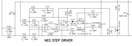
The diode in parallel with the gate resistor looks like it is drawn backwards.
I get clean turn-offs with 6µS pulse widths from that circuit. I use P-ch devices on the positive rail though, I don't need that much current(no bootstap cap needed either). I use a common-base level-shift transistor, no opto stuff.
I get clean turn-offs with 6µS pulse widths from that circuit. I use P-ch devices on the positive rail though, I don't need that much current(no bootstap cap needed either). I use a common-base level-shift transistor, no opto stuff.
In previous thread i think you were talking about the amp not class-H circuit....
In this Class-H ,
The diode is use to Turn-ON the Mosfet Faster , to eliminate premature Clipping...and the Turn off is kept slow to get seamless transfer.....QSC/Crest all uses faster-Turn-ON for the Switch...
The optos makes the circuit less prone to Switching artifacts arising within the circuit and also makes the Level-shifting much easier
For High power amps, P-channel switch doesnot hold good due to its High I2R losses due to Higher RDS and also they cost higher as compared to N-channel ones.....
K a n w a r
I wouldn't like to disappoint you, but I think that there are better ways to do it, particularly, there are (softer) ways to do it with minium disturbance to the main feedback loop as TIM may arise...
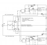
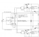
Also, you are going to get quite bad distortion and terrible global feedback loop disturbance by changing the supply rails of the whole amplifier, so what you should change are only the drain voltages at the output devices (while keeping the rest always on the highest rails). That in turn is going to be a bit difficult to implement properly in the lower bank of your N-channel topology.
Also, you are going to get quite bad distortion and terrible global feedback loop disturbance by changing the supply rails of the whole amplifier, so what you should change are only the drain voltages at the output devices (while keeping the rest always on the highest rails). That in turn is going to be a bit difficult to implement properly in the lower bank of your N-channel topology.
Hi Kanwar,
Eva has an excellent point there. If you look at the Carver designs, you will see they run off non-switched supplies. Only the output stage gets hit with variable voltages.
I think varying all the supplies will upset the amplifier dynamically. Best to avoid doing that. It does mean that the dissipation goes up in some of the small signal stages.
-Chirs
Well, Carver uses class G output stage series stacking for the transition to the second tier and class H rail switching with controlled slope for the transition to the third tier. That's indeed a quite clever approach taking the best of the two worlds.
Anyway, controlled slope is what I was talikg about.
BTW: Chris, do you have schematics for AB international 1100 models? they use +-50V and +-100V rail switching, and they allow the rails to fall to ground to improve reactive load handling, yet their switching circuit is quite simple. I had to repair one of these some time ago but I hadn't enough time to draw an schematic. I only remember that they used zener references and fully discrete switching with bipolar transistors.
Hi Eva,
I've repaired a couple way back in time (I'm not that old Clem! ), but don't recall too much about them. I did some searching for you but have not come across any free downloads.
Allowing the rails to go to ground is interesting. I'll bet that's stumped more than one tech!
Carvers were very interesting amps. Because of the design I found most users mis-applied the amps. Carver amp + generators + Caribana = angry non-pro sound guy.
-Chris
I've repaired a couple way back in time (I'm not that old Clem!
), but don't recall too much about them. I did some searching for you but have not come across any free downloads.Allowing the rails to go to ground is interesting. I'll bet that's stumped more than one tech!
Carvers were very interesting amps. Because of the design I found most users mis-applied the amps. Carver amp + generators + Caribana = angry non-pro sound guy.
-Chris
- Home
- Amplifiers
- Solid State
- The Class - H Amplifier