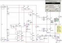
I found a curcuit from one of my text books (Sedra/Smith :Microelectronic Circuits 4th ed.), and I just started to fool around. After some modifications I ended up with a 180W power amp with MOSFET outputs.
It probably contain some flaws and I thought some of you on this forum could come up with some ideas to make it better or if this won't work at all.
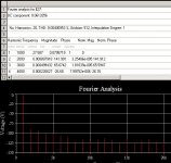
The sim says it will work fine and with good S/N and THD numbers, but I won't trust that....
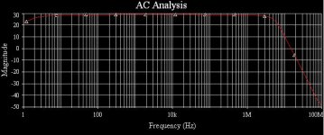
The curcuit shows good stability and great bandwith. The only thing I don't really trust is the emitter follower. I calculated a power dissipation of about 0,25 watts, but the MOSFETS will draw some current at higher frequencies (input cap= 1275pF per MOSFET)...would a 1 watt BJT be sufficient? It should be...but then, that tepends again on the input signal frequency....
(Remember, my electronics skills are a bit rusty, be nice on me. I think no question can be stupid enough...)
And yes, degeneration resistors must be added for practical use...
It probably contain some flaws and I thought some of you on this forum could come up with some ideas to make it better or if this won't work at all.
The sim says it will work fine and with good S/N and THD numbers, but I won't trust that....
The curcuit shows good stability and great bandwith. The only thing I don't really trust is the emitter follower. I calculated a power dissipation of about 0,25 watts, but the MOSFETS will draw some current at higher frequencies (input cap= 1275pF per MOSFET)...would a 1 watt BJT be sufficient? It should be...but then, that tepends again on the input signal frequency....
(Remember, my electronics skills are a bit rusty, be nice on me. I think no question can be stupid enough...)
And yes, degeneration resistors must be added for practical use...
Attachments
Providing nicely reguated supply and well matched transistors it can be very nice. Topologically it is creative and pretty 'balanced', in practice you'll probably end up with some degeneration resistors for wilson mirrors (say 33R) and for output mosfets (say 0R22). To simplify Q16/22 don't do much, I'd throw away. And temp. sensing V souce.
cheers
cheers
First mistake
Stupidity shows no limits, Q12,Q13,Q21 have to be replaced. I exceeded the Vce max for these BJT's with ca 50 volts. (The rails where +/-35 volts to begin with)
Maybe the MJE240 will work as a replacement, but I`m a bit sceptic regarding the input impedance...I also found the KSC2628 (Fairchild semiconductors) wich looks even more suitable
I`ll have to do som math and sims when I come home from work...
See my signature.... Hopefully soon though, I will probably purchase some output transistors and equipment for making PCB`s in a month or two. I`ve just finished building a power supply for testing my designs (+/- 35 volts, 500VA).
The problem is that I have 3 designs I would like to build, but I haven`t decided wich one to build first...probably this one
http://www.diyaudio.com/forums/showthread.php?s=&threadid=69442. I`m a but curious about why so many people favor designs without global feedback...plus I get full balancing...if it works...
In the mean time I`ll stick to my sim...better than nothing, but misleading in a lot of cases for sure..
. Hopefully soon though, I will probably purchase some output transistors and equipment for making PCB`s in a month or two. I`ve just finished building a power supply for testing my designs (+/- 35 volts, 500VA).The problem is that I have 3 designs I would like to build, but I haven`t decided wich one to build first...probably this one
http://www.diyaudio.com/forums/showthread.php?s=&threadid=69442. I`m a but curious about why so many people favor designs without global feedback...plus I get full balancing...if it works...
In the mean time I`ll stick to my sim...better than nothing, but misleading in a lot of cases for sure..
Hi again PanzerLord (whats your name btw?),
it's not to often you have been here around for a while, nice to see you back with lot of new ideas (as in your newest thread)!
It looks interesting, I would also like to try something like that, or att least have feedback from VAS.
I recognize myself in your words, having too many ideas I don't know which project I should start!
One idea I have is to use output transistors mounted on a motherboard while having input stage and VAS stage on separate daughterboards one can switch between to evaluate.
Cheers Michael
Re: First mistake
Have you looked at KSC2784 and KSA1174 from Fairchild for use as small signal instead of 2N5551, 2N5401? High linear gain but definitely small signal. (and 120V Vce low noise)
PanzerLord said:Stupidity shows no limits, Q12,Q13,Q21 have to be replaced. I exceeded the Vce max for these BJT's with ca 50 volts. (The rails where +/-35 volts to begin with)
Maybe the MJE240 will work as a replacement, but I`m a bit sceptic regarding the input impedance...I also found the KSC2628 (Fairchild semiconductors) wich looks even more suitable
I`ll have to do som math and sims when I come home from work...
Have you looked at KSC2784 and KSA1174 from Fairchild for use as small signal instead of 2N5551, 2N5401? High linear gain but definitely small signal. (and 120V Vce low noise)
notes:
1.) add input capacitance of 100F for simulation purposes. as it stands, the terminal sees 0ohm DC impedance to ground, creating an artificial imbalence. 100F is insignifigant above a microhertz...
2.) V6? wouldn't you need to determine how to implement this.
3.) i assume this thing has a stable DC bias point. i can't seem to find any way to really find it though.
4.) very high gain amps can have issues with component matching that does not show up in simulations that use exact match components. thermal issues as well.
5.) 1M resistors may be a bit noisy. i try to keep resistors to 100k or less for best results.
From looking at this, i assume it was a design for an IC. i'm not familiar with the current feedack or biasing shown here. assuming Q3 changes current, Q1 will as well as 22, 16 and 10. changing current here changes current in 14,15 and 8,9. that changes Q3 = feedback.
overall, i'd probably not reccomend the design with discrete components.
I didn`t really intend to build this, at least not in the beginning(though I might test i out on a vero or something). I did modify (a lot) it however (se further down), I`ll see what happens with the new one.
Input cap must be implemented yes.
V6 would be a standard amplified diode (bjt output), or pot/resistor for FET`s.
I had some trouble with dc offset, but a DC servo solved the problem.
I think the main problem with this circuit would be the component matching, not impossible, but difficult.
I did a sim (not posted) with resistors in the legs of the diff stage and a balanced folded cascode (single ended out) that showed similar results as this one. But the probability for the new one to work with a discrete layout is much higher because component matching wouldn`t be that critical.
I could post the new circuit if you like. But that`ll have to wait till I get home from work.
Hi Panzerlord ! Have you finished built your amp which was post before , a amp is similar Blameless ?
Are you using feedforward common mode ? I think you need dual-tst and more use quad-tst
I think we should do sim with high frequency signal , because THD often increase with high frequency signal
Are you using feedforward common mode ? I think you need dual-tst and more use quad-tst
I think we should do sim with high frequency signal , because THD often increase with high frequency signal
- Status
- This old topic is closed. If you want to reopen this topic, contact a moderator using the "Report Post" button.
- Home
- Amplifiers
- Solid State
- 180W folded cascode (just fooling around)