Would the amp even work if I had 3 out of 4 transistors in backwards? I still am not sure about the actual pinouts, but correct me if I'm wrong.
Maybe I'm missing something on the data sheets that tells you that the BC41x are different from the BC550/560. Is there any way to tell which pin is the collector and which pin is the emitter? Thanks.
Maybe I'm missing something on the data sheets that tells you that the BC41x are different from the BC550/560. Is there any way to tell which pin is the collector and which pin is the emitter? Thanks.
From all that I can gather, the transistors are in the right orientation.
http://hamradio.lakki.iki.fi/new/Datasheets/transistor_pinouts/
and the bc550 data sheet previously posted agree. i put them in the same orientation as the burned out transistors, and they look to me just like the other channel. I'm about halfway done with a makeshift schematic... so it should be up in a couple days.
-phil
If you flip the emitter and the collector you'll get a transistor with Hfe of 3-10 and Vce of 5-15 volts. It might work rather good to poorly or not at all.philibuster said:Would the amp even work if I had 3 out of 4 transistors in backwards?
If you flip the emitter and the collector you'll get a transistor with Hfe of 3-10 and Vce of 5-15 volts. It might work rather good to poorly or not at all.
I agree with Per-Anders. The BC413..416 are vintage transistors. I wouldn't wonder, if the pins are swapped to the nowadays available datasheets. I'd use a DMM with hfe tester and compare the original ones to the BC550/560.
Also, the distortion increases the same amount as the input signal as the preamp is turned up. I think this means it's not crossover distortion; am I correct in saying this?
I'm pretty sure the pinouts are correct. I've checked the data sheets many times over. feel free to correct me.
I have some A1085's on order (TR6,7,8 in the picture).
When I blew up the amp, I shorted R44 to the wire jumper that's next to it. I think R44 is connected to TR12, one of the drivers, and TR8, part of the input buffer? The wire jumper connects to TR7. So perhaps TR7 and TR8 are dead as well.
Does anybody know where to source 2SA1085's? Everyone I've seen is out of stock. I think one of these went too. Thanks.
-phil
The volume matching is pretty good between both channels. does this help diagnose? Thanks
I'd use a DMM with hfe tester and compare the original ones to the BC550/560.
I don't have such equipment. Anything i can build? on a breadboard or what not? Thanks.
-phil
Does this amp have a differential pair on the input?? and if so have you replaced those transistors??
I had a problem with my amp where I was getting bad distortion (about 1.3% THD) on one channel, it was after I had changed out all the transistors with hfe matched pairs, but on installation of the new ones I got a very fine strand of copper wire forming a bridge between two legs of one of the driver transistors (must have done some careless wire stripping over the circuit board).... anyway I found the bridge (the amp had 60V DC on the output before I fixed that) and I found I had the distortion problem.... I resoldered everything, tore my hair out for a week or two, and then I finaly thought to myself.... NFB reduces distortion what if something was wrong with the transistors in the diff pair where the feedback is applied. I pulled out the two transistors which had previously been matched for hfe and they were no longer anywhere near matched, and had dropped significantly in hfe value. Put a new pair in and the THD went from 1.3% to .04% (which is pretty standard for this amp).
I guess the bottom line is the transistors were not fried but were certainly damaged (I assume due to the problem with the driver stage), hence the circuit still worked but not as it should have.
anyway as you don't have a shcematic I don't know if this is even relevant") but hopefully it may be of use
but hopefully it may be of use
Tony.
I had a problem with my amp where I was getting bad distortion (about 1.3% THD) on one channel, it was after I had changed out all the transistors with hfe matched pairs, but on installation of the new ones I got a very fine strand of copper wire forming a bridge between two legs of one of the driver transistors (must have done some careless wire stripping over the circuit board).... anyway I found the bridge (the amp had 60V DC on the output before I fixed that) and I found I had the distortion problem.... I resoldered everything, tore my hair out for a week or two, and then I finaly thought to myself.... NFB reduces distortion what if something was wrong with the transistors in the diff pair where the feedback is applied. I pulled out the two transistors which had previously been matched for hfe and they were no longer anywhere near matched, and had dropped significantly in hfe value. Put a new pair in and the THD went from 1.3% to .04% (which is pretty standard for this amp).
I guess the bottom line is the transistors were not fried but were certainly damaged (I assume due to the problem with the driver stage), hence the circuit still worked but not as it should have.
anyway as you don't have a shcematic I don't know if this is even relevant
but hopefully it may be of use Tony.
I finished the schematic. I do have a differential input pair, with feedback through a little filter network and through the input with a filter network also. Anyway, i'll try to upload a scan or something tonight when I have my camera. I could draw it out in something, but I think scanning it is better (easier). I've definitely didn't replace a couple components in the path that I shorted. I still need to source a few A1085E transistors. Anybody got a supplier that has them in stock or know of a modern equivalent? Thanks for the help, this has really been good.
here it is. there are a few errors, but I'm tired, and it's late. so, the transistors are mislabeled as weird types, and the zeners are the wrong types as well. it's messy, and has no component values, but it's representative; it's not supposed to be reproduceable. THanks for the patience, guys.
-phil
-phil
Attachments
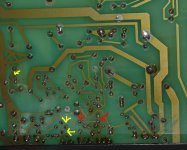
At first sight, pinouts appear to be CBE. I think I've seen one pair of transistors forming a differential pair, and another pair forming a current mirror (one of them is connected as a diode). However, there is something weird in that layout: the collector pins from the driver transistors appear to be uncomitted.
Sorry...
When I took that picture, I didn't get a good view of the tracks behind that little black thing. The drivers have tracks, you just can't see them from that vantage point. Pretty good sleight of hand by me. Anyway, they're detailed in the schematic I posted. TR12 is the center driver, TR13 is the one on the right, from the top view, and TR14 is the one on the left in the top view. What's a current mirror? What does its schematic look like? Thanks.
-phil
just looked up current mirror... and the article I found said that the hFE's should be matched! whoops, because I replaced one BC416, but not the other in the current mirror pair! This may be causing my headache. Or, it could be the diff. input pair. Either way, I have more soldering to do. Thanks for the help.
It's probably more the desoldering.... Since I bought a decent solder sucker and desolder braid (I use the solder sucker first then the braid) I've had a lot less problems with tracks lifting. Also if you have a variable temp iron, sometimes a higher temp is good for desoldering (or soldering for that matter), even though it is hotter, you have to keep apply the heat for less time (especially with wide tracks/thick leads.
Tony.
Tony.
I have a 40W iron... but it's a honking tip. I should really get a good tip. I used some solder wick braid stuff, but it still just makes the pads lift. I've tried cutting the leads, but still, lifting pads. I guess point to point wiring isn't too horrible, but it makes for an ugly mess.
- Status
- This old topic is closed. If you want to reopen this topic, contact a moderator using the "Report Post" button.
- Home
- Amplifiers
- Solid State
- Diagnose my problem? Replaced transistors and now high THD