Have a look in the chip amp forum as it doesn't get any easier. Check out the LM3875 kit here.
http://www.chipamp.com/
http://www.chipamp.com/
You son't have ot be the "best" at soldering but you do need ot learn how.
Here's a couple of tips that have worked for me.
Let the iron get completely hot before you start.
Keep the tip clean by wiping it on a damp sponge frequently.
Tin the tip lightly with solder.
I like a pointed tip for getting into tight places.
Use fine gauge solder.
I use a 40 watt iron so I don't have to stay on the part very long.
Make sure you don't move the part while it is cooling.
For amps, you might also want to look at ESP Audio. Rod offers some pretty easy to build amps that sound very good.
Blessings Terry
For amps, you might also want to look at ESP Audio. Rod offers some pretty easy to build amps that sound very good
What Terry said. The P3A and P101 are nice amps and easy to build.
SteveA
SteveA said:
What Terry said. The P3A and P101 are nice amps and easy to build.
SteveA
For an absolutely beginner diyer they aren't easy-to-bulid amps!
If I were Turboman I would construct a chip amp with TDA2003, or any similar cheap and small IC.
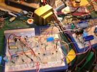
I call this one the Radio Shack special. Actually, I just created it today.  But, it does sound great, with lots of body and has a pretty good PSRR, with virtually no hissssss or ffffttppptptptpptttp. My current job requires me to travel(nothing to do with electronics ) and I was thinking that I would like to have a small 2 X say 25W to take with me because I have all my music on my laptop when I travel and it is just not quite loud enough. However, it must sound acurate at lower volumes and not have parts of PS noise poisoning the delicate small output signal. It also has to crank...realativily. This could drive it 4 Ohms each channel, using 2 PS transformers of course.
So.......it is not too bad for being designed around using the Radio Shack speacial 12.6V_0V_12.6 @2A, 10$ transformer and some 1A diodes, a bridge and some caps you can get at Radio Shack for, belive it or not, reasonable retail prices. Of course some of the devices in this circuit don't come from radio shack. Anyway, it can be made to work on a P-O-S proto-board. The heatsink here is way undersized, but allows me to use it easily in the P_O_S protoboard. Just can't crank but for a short time. This does let me test the thermal compensation though....looks good as long as you don't use bare minimum output bias because the temp. coefficient is just slightly negative. I kind of like this to keep from thermal runaway.
I did notice a small occilation of 5mV P-P of about 2.6MHz, but I think the fact that the circuit has no metal shielding, and is on a P-O-S proto-board, could be the cause of this.
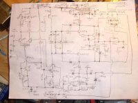
This is basically a common amp AB circuit so no point holding out on everyone.......
But, it does sound great, with lots of body and has a pretty good PSRR, with virtually no hissssss or ffffttppptptptpptttp. My current job requires me to travel(nothing to do with electronics ) and I was thinking that I would like to have a small 2 X say 25W to take with me because I have all my music on my laptop when I travel and it is just not quite loud enough. However, it must sound acurate at lower volumes and not have parts of PS noise poisoning the delicate small output signal. It also has to crank...realativily. This could drive it 4 Ohms each channel, using 2 PS transformers of course. So.......it is not too bad for being designed around using the Radio Shack speacial 12.6V_0V_12.6 @2A, 10$ transformer and some 1A diodes, a bridge and some caps you can get at Radio Shack for, belive it or not, reasonable retail prices. Of course some of the devices in this circuit don't come from radio shack. Anyway, it can be made to work on a P-O-S proto-board. The heatsink here is way undersized, but allows me to use it easily in the P_O_S protoboard. Just can't crank but for a short time.
This does let me test the thermal compensation though....looks good as long as you don't use bare minimum output bias because the temp. coefficient is just slightly negative. I kind of like this to keep from thermal runaway. I did notice a small occilation of 5mV P-P of about 2.6MHz, but I think the fact that the circuit has no metal shielding, and is on a P-O-S proto-board, could be the cause of this.
This is basically a common amp AB circuit so no point holding out on everyone.......
Attachments
edl said:
For an absolutely beginner diyer they aren't easy-to-bulid amps!
If I were Turboman I would construct a chip amp with TDA2003, or any similar cheap and small IC.
I've never built a chip amp. I suppose they are easier to build. I guess it depends on how much he wants to learn on the first amp. The P101 was my first amp and I had to ask a lot of questions, but as a result I learned a lot. Everything mounts on the PCB so IMO that makes it a fairly easy amp to build. It sounds great and has plenty of power. I don't know how that compares to a chip amp.
I have heard mixed reviews about the chip amps. Some folks swear they sound wonderful and others seem disappointed.
If his goal is just to make a working amp, I guess the chip amps would be the way to go. I think he will learn more building the P101.
Blessings, Terry
CBS240 said:I call this one the Radio Shack special.
Impressive piece of paper.
Never seen a D44H11/D45H11 output stage.
Makes me wonder how that sounds with a doubled output, a 0.70 C/W heatsink and 1 amp bias.
jacco vermeulen said:
Never seen a D44H11/D45H11 output stage.
Makes me wonder how that sounds with a doubled output, a 0.70 C/W heatsink and 1 amp bias.
Actually, I think I would rather make another seperate channel than double up the outputs, each with sepearate PS. Since SMD's are much cheaper, all the other parts are not a problem if you can solder.
I have quite a few of the D44H11/D45H11 so I need something 'general purpose' to use them for. They don't sound bad though. I may try to push them on a heavier load like 3Ohms or maybe 2...?...
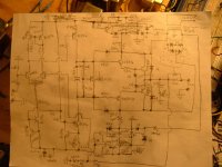
 Since there is only 18V, probably like 15V when loaded, it should stay within the SOA, if reactance doesn't kill it. I may start a "hard copy" tomarrow.
And bias is much lower than 1A...more like 30-40mA.
minor update, if anyone interested,
When driving about 2 Ohms, the PS caps and transformer current is obviously a limiting factor. It seems to be the major limiting factor here. Load is two 4Ohm 15" 4way 120W speakers in paralell, nice mixed load with lots of freq. vs phase differences. Output voltage and rail voltage meet at about 12V. I only have 6800uF filter caps though, they should be like 2 or 3X that. Still it is a lot of current for these little devices even running hot. I also tested the thermal bias stability by puting the that little heatsink (in post #10) in the freezer for a while, then cranked up to get it really hot, to compare the difference in bias current at the extreams. Didn't change too much, about 10mA or so. I also added some small caps that seem to add some extra RF stability. Protoboards don't help RF stability. 
I may try a more robust PS and see if the outputs expode. I suppose they either will or not, at least I would know the limits.
I guess it outputs about 30W in to 2Ohms. That's only like 11 or 12V peak. It will go to 16V peak on 4Ohms before clipped by the PS rail. I'm sure larger filter caps will help this though.
For a cheap little circuit slapped together on a protoboard, it works pretty good.
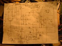
EDIT> 470pf cap between the collectors of diff amp could affect higher freq. responce and doesn't seem to affect stability that much as the .1uf on the output does and can be deleted.
When driving about 2 Ohms, the PS caps and transformer current is obviously a limiting factor. It seems to be the major limiting factor here. Load is two 4Ohm 15" 4way 120W speakers in paralell, nice mixed load with lots of freq. vs phase differences. Output voltage and rail voltage meet at about 12V. I only have 6800uF filter caps though, they should be like 2 or 3X that. Still it is a lot of current for these little devices even running hot. I also tested the thermal bias stability by puting the that little heatsink (in post #10) in the freezer for a while, then cranked up to get it really hot, to compare the difference in bias current at the extreams. Didn't change too much, about 10mA or so. I also added some small caps that seem to add some extra RF stability. Protoboards don't help RF stability.
I may try a more robust PS and see if the outputs expode. I suppose they either will or not, at least I would know the limits.
I guess it outputs about 30W in to 2Ohms. That's only like 11 or 12V peak. It will go to 16V peak on 4Ohms before clipped by the PS rail. I'm sure larger filter caps will help this though.
For a cheap little circuit slapped together on a protoboard, it works pretty good.
EDIT> 470pf cap between the collectors of diff amp could affect higher freq. responce and doesn't seem to affect stability that much as the .1uf on the output does and can be deleted.
Attachments
- Status
- This old topic is closed. If you want to reopen this topic, contact a moderator using the "Report Post" button.
- Home
- Amplifiers
- Solid State
- Easy to build amp