I`m going to built a double output stage project68...As quoted in the article...........
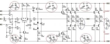
"the doubled output stage, with Q9, Q10, Q11 and Q12 simply repeated - along with the emitter resistors. Each 1/2 stage has its own zobel network and bypass caps as shown, as this is the arrangement "
Should it be as this shown below ?
Note: I added 2 output diodes on the output to protect power transistors from reverse voltage.
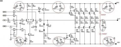
Attachments
mastertech said:hahaha youre a funny guy!! you made me laugh to death
cheers
Why, I`m not into electronics, I`m still a newbe btw
what are you saying just because youre a newbe you are not
funny, youre funny ideas, you know,youve ruined rods amp
isnt that funny,you know, if i was Rod elliot i would kick your
*** (kidding) for ruining my nice amp what are you into making jokes of us , keep up the good work funny man/woman!!
cheers
funny, youre funny ideas, you know,youve ruined rods amp
isnt that funny,you know, if i was Rod elliot i would kick your
*** (kidding) for ruining my nice amp what are you into making jokes of us , keep up the good work funny man/woman!!
cheers
mastertech said:what are you saying just because youre a newbe you are not
funny, youre funny ideas, you know,youve ruined rods amp
isnt that funny,you know, if i was Rod elliot i would kick your
*** (kidding) for ruining my nice amp what are you into making jokes of us , keep up the good work funny man/woman!!
cheers
I`m not making any jokes as you are thinking.
How whould you join these two circuits ?
Attachments
Yes leander your idea looks fine, I can't understand what mastertech was on about, best ignore him. The output catch diodes are a good mod as well, but they must be powerful devices.
Only thing I'd say is that as a newbie you'd be much better off with a simpler project such as P3a as a first project. So much more to consider in the design of a powerful amp, and so much more to blow up and lose you a lot of money.
Only thing I'd say is that as a newbie you'd be much better off with a simpler project such as P3a as a first project. So much more to consider in the design of a powerful amp, and so much more to blow up and lose you a lot of money.
mastertech..please behave according to our guidelines and rules.
http://www.diyaudio.com/forums/announcement.php?s=&announcementid=4&forumid=51
http://www.diyaudio.com/forums/announcement.php?s=&announcementid=4&forumid=51
mastertech said:i appologise to Mr leander, but try to build the circuit as the
first attachement shows and you'll see what i mean
my mistake, i havent read Rod's excellent Articles
Why not spare leander any trouble and tell him (and the rest of us) what you find wrong?
\Jens
Hi Jens good to see you back, how are you doing buddy
we are talkin about the first attachemnt right?
there can not be current throu the load because
both ends of the load are at the same voltage even with
signal
second the decouplers of the rails are spaced equaly on the
rails and that creates power nodes which in realation to
ground nodes could result in some unexpected results
third the zobel networks shouldnt be a problem
fourth second pair of rail clamp diodes should be connected
to the other side output stage if desired protected
fifth for super balance and low distortion an amplified diode
network bias should be used instead of the diodes
i hope this helps
jens please correct me should i be wrong cause my eyesight
is shortshighted and monitor strain doesnt make it any better
cheers
Load connection
Mastertech,
I believe that the "output" is shown in the first picture as a "node" instead of a load.
Thanks
Fabien
mastertech said:...there can not be current throu the load because
both ends of the load are at the same voltage even with
signal...
jens please correct me should i be wrong cause my eyesight
is shortshighted and monitor strain doesnt make it any better
cheers
Mastertech,
I believe that the "output" is shown in the first picture as a "node" instead of a load.
Thanks
Fabien
mastertech said:
second the decouplers of the rails are spaced equaly on the
rails and that creates power nodes which in realation to
ground nodes could result in some unexpected results
Should they be grouped at one point on the rails?
mastertech said:Hi Jens good to see you back, how are you doing buddy
we are talkin about the first attachemnt right?
there can not be current throu the load because
both ends of the load are at the same voltage even with
signal
second the decouplers of the rails are spaced equaly on the
rails and that creates power nodes which in realation to
ground nodes could result in some unexpected results
third the zobel networks shouldnt be a problem
fourth second pair of rail clamp diodes should be connected
to the other side output stage if desired protected
fifth for super balance and low distortion an amplified diode
network bias should be used instead of the diodes
i hope this helps
jens please correct me should i be wrong cause my eyesight
is shortshighted and monitor strain doesnt make it any better
cheers
1) I agree the drawing is not the best in the world, but I think that the out is one node at that the output voltage should be taken with respect to ground.
2) That depends on how you implement it - fat power traces and a ground-plane is a must.
3) One zobel should be enough
4) Please explain further
5) This is the topology that Rod has used - It is his design and it seems to work ok.
leander-
Should they be grouped at one point on the rails?
i think jens is helpful here!
jen-
2) That depends on how you implement it - fat power traces and a ground-plane are a must.
second what kind of distortion are we looking as my friend
D Self is a starpoint fanatic
AS you know considering i am a commercial amp developer i cant
disclose here any information regarding our grounding systems
as youve said yourself youre a newbie and top performance is not your first priority even with no consideration
to ground you shouldnt have any problem with your circuit as it is
or infact without even starpoint as my friend D Self advocates
cheers guys
- Status
- This old topic is closed. If you want to reopen this topic, contact a moderator using the "Report Post" button.
- Home
- Amplifiers
- Solid State
- Double Output Stage for ESP project68