I have a gorgeous Sansui 5000. It is a 5000 in a black case, (it is not an 5000A nor a 5000X). I have one problem, and only one problem (everything else works 100% perfectly). When used in FM or FM Stereo there is no volume. If I turn the Level Adjust all the way clockwise and turn the volume all the way up, I can just barely here the sound. The Tuner appears to be working fine and I am getting level 5+ signals via an Audio FM Antenna. I am hoping the problem is something both common and obvious to someone because I am very good with a soldering iron. My weakness is an inability to read schematics well (other than knowing what a component is when I see it), and I have no diagnostic equipment. I have the service manual, so if someone was to tell me that it needs a new "xyz" transistor, (or resistor, capacitor, etc) on the "123" board, I could do the repair. Please help! (Thanks in advance).
-----------------------------------------------anatech said:Hi gwyz,
Two simple things to check. The tape monitor switch (out) and the main in / pre out jumpers (if equipped) on the back panel.
-Chris
Hi Chris,
Thank you for the reply. Unfortunately, it's not something simple like that. But to answer the question: First, it does not have jumper blocks. Second, when the Tape Monitor switch is in the IN position, the AM also does not work.
What I find curious is that the Level Adjust in the back had already been turned all the way up, suggesting that someone else had already tried and given up. This is an ebay purchase. This morning I wrote to the seller, who has very positive feedback and guaranteed the unit. I'd rather fix it because I paid $49 for it, and the shipping expense makes it hardly worth returning. The reason I need to fix it myself is because I live on the East Coast where the shop rates make professional repair too expensive an option.
If I just knew which part was bad I really could fix it myself.
Do you have any other suggestions? I *really* appreciated the time you took to reply. Thank you *very* much.
Sincerely,
Gregg
Hi Gregg,
One common failure I've seen is the MPX IC failing. This may or may not be true in your case. The composite FM audio signal goes into this chip and comes out as a stereo signal. I have also seen the small filter film caps on the output short. It would be unusual to find both shorted, but I did once.
Normally I would troubleshoot this with an oscilloscope. Can you post the schematic of the MPX section, or email it to me? If you know someone with a 'scope or have access to one, let me know.
-Chris
---------------------------------------anatech said:Hi Gregg,
One common failure I've seen is the MPX IC failing. This may or may not be true in your case. The composite FM audio signal goes into this chip and comes out as a stereo signal. I have also seen the small filter film caps on the output short. It would be unusual to find both shorted, but I did once.
Normally I would troubleshoot this with an oscilloscope. Can you post the schematic of the MPX section, or email it to me? If you know someone with a 'scope or have access to one, let me know.
-Chris
Hi Chris,
I can't thank you enough for trying to help. Unfortunately, I do not have a scanner. I do have the schematic right in front of me. The MPX circuit is showing the following parts that have to do with amplification. (Note that where I put parenthesis it means there is a "small" number to the low right of the preceeding letter):
----------------------
From the Antenna it goes to the (TUNER?) "FM PACK" (board F-1011). The first amp is identified as a High Frequency Amp and the circuit is as follows :
High Frequency Amp = FET101 = (Parts list does not list this part)
High Frequency Amp = TR101 = (Parts list does not list this part)
Mixer = TR102 = (Parts list does not list this part)
Oscillator = TR103 = (Parts list does not list this part)
END "FM PACK"
-----------------------
BEGIN first section of F-1006 board (identified on schematic as F-1005)
IC201 = TC201 = uA703E
IC202 = TC202 = MA703E
IC203 = TC203 = MA703E
IC204 = TC204 = MA703E
END F-1005
------------------------
BEGIN MULTIPLEX STEREO - (Second section of F-1006 board)
"Composite Signal Amp"
TR401 = 19KHz Amp = 2SC536V(1)E(2) = Si N-P-N
TR402 = 19KHz AMP = 2SC536V(1)E(2) = Si N-P-N
TR403 = 38KHz Amp = 2SC536V(1)E(2) = Si N-P-N
TR404 = (not identified) = 2SC536V(1)G(2) = Si N-P-N
TR405 = 19KHz Amp = 2SC536V(1)E(2) = Si N-P-N
TR406, 7, 8 & 9 are all "DC Amp" and appear to control the signal gauges which are working fine.
END MULTIPLEX STEREO - (Begin Switch Control circuit)
----------------------------
I hope this info was of some help. I read at another site someone posted a comment that all parts for the Sansui 5000 are available *except* the IC chips.
I do not have an oscilloscope, nor do I know anyone.
Sincerely,
Gregg
Hi Gregg,
At this point, you really need to be able to trace the signal to find the fault. I will guess at the MPX section as it could kill both channels. Do you get a stereo beacon when tuned to a strong station?
I sent you a portion of a schematic to compare to your manual, just the MPX portion. My feeling is that you need some assistance from someone with some test equipment. Let me know the answer to the beacon question at least.
-Chris
This makes me think the whole tuner section is ok and the problem might be somewhere in a setting of the knobs on the front. Perhaps this is just too obvious to be true.gwyz said:If I turn the Level Adjust all the way clockwise and turn the volume all the way up, I can just barely here the sound.
/Hugo
")
Re: Re: Need help with Sansui 5000
Hi Hugo,
Unfortunately, the "obvious" type problems would also be happening when in AM mode. The problem is only FM (and FM Stereo). However, I *have* tried pressing every button and combinations of buttons such as Tape Monitor, Stereo Only, Mute, etc... The knobs and buttons confuse my wife, but not me. I grew up with this equipment. I can literally set this thing up with my eyes closed.
Thanks for the offer though. I *do* appreciate every suggestion I get from anyone who takes the time to offer it.
Thank you.
Sincerely,
Gregg
---------------------------------------Netlist said:
This makes me think the whole tuner section is ok and the problem might be somewhere in a setting of the knobs on the front. Perhaps this is just too obvious to be true.
/Hugo
Hi Hugo,
Unfortunately, the "obvious" type problems would also be happening when in AM mode. The problem is only FM (and FM Stereo). However, I *have* tried pressing every button and combinations of buttons such as Tape Monitor, Stereo Only, Mute, etc... The knobs and buttons confuse my wife, but not me. I grew up with this equipment. I can literally set this thing up with my eyes closed.
Thanks for the offer though. I *do* appreciate every suggestion I get from anyone who takes the time to offer it.
Thank you.
Sincerely,
Gregg
-----------------------------------anatech said:Hi Gregg,
At this point, you really need to be able to trace the signal to find the fault. I will guess at the MPX section as it could kill both channels. Do you get a stereo beacon when tuned to a strong station?
I sent you a portion of a schematic to compare to your manual, just the MPX portion. My feeling is that you need some assistance from someone with some test equipment. Let me know the answer to the beacon question at least.
-Chris
Hi Chris,
I sent you a reply via email. Yes, the schematic you sent is the correct one.
By the way, I do have simple test equipment like a voltmeter; (I built it myself from a Heathkit I bought in 1975). I also have a transistor tester, but you need to plug the transistor in. The thing actually *fixed* a transistor once. It must have been stuck somehow. It didn't work the first time I tested it, but it did the second time I tested it. Then after that it worked when I put it back in the power supply I had pulled it from.
The tester also tests FETs, Diodes, SCRs, and LEDs. However, I've only used it to test transistors.
So, what's next?
Thanks *MUCH*.
Sincerely,
Gregg
To Hugo,
I will tell Chris you asked for the schematic.
------------------------------------------------------
To Chris,
You asked me if the Stereo light was lighting up.
NOW WE ARE GETTING SOMEWHERE!!!
No, it does not. I pulled the bulb and it tests good. Okay, remember I told you that with the Level Adjust (in the back) all the way up, and the front volume all the way up, I can just barely hear the FM Radio? Well, if I push the "Stereo Only" button in I no longer hear any sound. (Note: I have a signal strength of 5+ on a scale of 1 - 6. There is no doubt that I *should* be getting a couple of Stereo signals). There is no sound. However, after a few seconds there is nothing but static. The static noise stays at the exact same level as I turn the tuner dial. It does not fade in and out, nor change in any way as "reception" static normally sounds.
If I press the "Stereo Only" button back "out," I again here faint sound across the dial. (I hear each station faintly). So, I assume I've got a bad MPX circuit, yes?
Is it possible to bypass the problem? I could live with a Mono tuner. And as I stated in my email, I could give up altogether and buy an external Tuner. I'm worried that my wife (who wants to push *ONE* button) will get disgusted with a complicated setup. She can't even turn on the TV in the bedroom because of a dual DVD setup, with the TV used as a Monitor (which needs to stay on channel 3).
Come to think of it, if I can't fix this tuner section I will have to bail out of this Sansui altogether. I just saw an image in my mind of my wife cursing at the stereo over not being able to turn on the Radio!
In the mean time, I noticed that out of the 4 IC's the last two are made of metal and look newer. The reason I wonder if they could have been replaced is because according to the parts sheet, the #3 and #4 IC is the same part number as the #2 IC. Yet the number #1 and #2 IC's are both Ceramic. When I say the #3 and #4 IC's "look newer" I mean their wires look "new clean" whereas the #1 and #2 IC have a little oxidation.
Okay, what's next?
Thanks,
Gregg
Hi Gregg,
Okay, so leave the stereo only button out. Turn the muting level down and try turning the control on the back down. All while tuned into a strong station.
What we need to check is TP403 for an audio signal, TR401 may be suspect, the audio should come from the emitter. C416 and 418 are in series with the signal, also L401 || C417 = filter and L402 (trap) to kill the 19KHz pilot. TR402 (19KHz) and TR403 (38KHz) process the carriers for the L-R information (the mono is L+R info). The matrix after D403~D406 combine these signals to give you L and R out.
The other thing to make sure is that TR401 is not biased off by the muting network. Make sure you have 7V at terminal 4J, and on the other side of R436 (4R7). If a filter cap shorts it will burn this resistor.
-Chris
-------------------------------anatech said:Hi Gregg,
Okay, so leave the stereo only button out. Turn the muting level down and try turning the control on the back down. All while tuned into a strong station.
What we need to check is TP403 for an audio signal, TR401 may be suspect, the audio should come from the emitter. C416 and 418 are in series with the signal, also L401 || C417 = filter and L402 (trap) to kill the 19KHz pilot. TR402 (19KHz) and TR403 (38KHz) process the carriers for the L-R information (the mono is L+R info). The matrix after D403~D406 combine these signals to give you L and R out.
The other thing to make sure is that TR401 is not biased off by the muting network. Make sure you have 7V at terminal 4J, and on the other side of R436 (4R7). If a filter cap shorts it will burn this resistor.
-Chris
Hi Chris,
Okay, this is where we separate the professionals from the "wannabe hacks."
I said I built an Multi Meter, I didn't say I knew how to use it. To make matters worse, it is analog, not digital. So, I can tell there is voltage, but not an exact measurement. Also, I don't understand anything you said in the first paragraph. I don't know how to check for an audio signal, etc... It would be easier for me to say what I do know. I know how to check for AC or DC current, and how to check for resistance. And with resistance I am only certain of open and closed circuits.
Also, it has been so long (20+ years) since I've messed with this stuff on this level. I was in an accident which messed up my memory. I frequently forget the simplest things, such as I forgot whether I am checking for AC or DC current. I am assuming I was supposed to check for AC current when checking for that 7 volts on R436. It is a HUGE resistor and it does not look burnt. I am getting a different voltage reading on either end of the resistor and terminal 4J. I don't know which end is "the other side" of R436, so I tested for voltage on both sides. I get two different readings. Since my meter switch only goes down to 15 volts AC, I was not certain of what the voltage readings were. I only know that there was more on one end than there was on the other; suggesting that the resistor is working.
With regard to the transistors... Again, I don't know how to check them other than to try my component tester. I began doing this last night and finished this morning. According to the tester, the following transistors have shorts:
TR401, 402, 403 and 404.
All of the other transistors on that circuit board test good. I repeated the tests on each transistor *dozens* of times to make sure I was making contact. When they failed they failed every time, and when they passed they passed every time.
All of the resistors look good, but I only tested the one you asked me to test (R436). Like I said, it's HUGE, not burnt, and it's showing different voltages on either side of it and terminal 4J.
Chris, I can take stuff apart and I can put it together in a neat and professional manner, but with regard to diagnostics I am *very* limited. Were it not for this component tester I bought I would not have been able to test the transistors. In fact, it is only because of my ability to make repairs that look very neat and professional, that I resist the label "hack."
Of interest, TR401 is acting like a capacitor when I test it with a Ohm Meter. Base 1 to Base 2, and Base 2 to Base 3, show an initial resistance of 10 and then slowly drift to 100. Note that the electricity is off on the unit. It has not been plugged in since last night. It is still showing the same reading as it did when I first pulled the plug; (it reads 10 then drifts to 100).
I don't know what that means. I was testing for an open circuit between each base when I found that reading. None of the other transistors do that. The others (both good and bad) show a reading of about 10 and then stay at 10.
Did that help? Should I just buy new transistors? If they are inexpensive is it worth replacing all of them. If they are expensive, then I would be better off replacing only the ones that tested bad. (Or should I look at it from that point of view regardless of price?).
Or should I be worried about what caused these transistors to go bad in the first place? Is there something else I should test that I am *capable* of testing? I realize it is frustrating enough to be doing this long distance, and my inadequacies on top of that fact only make matters worse. I apologize for that.
Sincerely,
Gregg
Hi Gregg,
So let's keep things simple. No problem. All measurements are with the negative lead connected to the chassis clost to the board. The unit is on and tuned to a strong station.
Please measure both sides of the 4R7 resistor, DC scale, we expect about 7 VDC. Let me know.
On the 15 V AC scale, measure TP403. Look for the needle bouncing slightly while tuned into a strong station. Let me know if the needle moves at all.
Again, on the lowest DC scale, measure the base of TR401. Let me know what you get.
Turn the control on the rear of the unit down, opposite where it is now, make sure the volume is not turned up. This may be a mute level control and full up may kill any signal. When it unmutes the set may work.
Let's ignore the resistance measurements for now.
-Chris
---------------------------anatech said:Hi Gregg,
So let's keep things simple. No problem. All measurements are with the negative lead connected to the chassis clost to the board. The unit is on and tuned to a strong station.
Please measure both sides of the 4R7 resistor, DC scale, we expect about 7 VDC. Let me know.
On the 15 V AC scale, measure TP403. Look for the needle bouncing slightly while tuned into a strong station. Let me know if the needle moves at all.
Again, on the lowest DC scale, measure the base of TR401. Let me know what you get.
Turn the control on the rear of the unit down, opposite where it is now, make sure the volume is not turned up. This may be a mute level control and full up may kill any signal. When it unmutes the set may work.
Let's ignore the resistance measurements for now.
-Chris
Hi Chris,
Okay, this experience has convinced me I need a digital Multi Meter. I got frustrated trying to figure out which set of lines and numbers corresponded to which voltage levels on the face of the Analog Meter. So, I am going to tell you what numbers it was reading if you were looking at the top numbers, which I believe is "Ohms."
Regarding the 4R7 (R436) resistor: With the Meter set to 3 volts DC, the black lead on chassis ground and the red lead on the side of the resistor with the colored bands, I get a reading of 100 on the Ohms scale. On the other side of the resistor I get a reading of 45 on the Ohms scale. With the Meter set to 15 volts DC, I get a reading which barely moves the needle around the 500 range on either side of the resistor. If I try 0.3 Volts, on the colored bands side I get 3 on the Ohms scale, but on the other side it pegs the needle below zero.
I got a little confused with the word "Base" on the transistor question because my component tester refers to all three transistor pins as "base" pins. If you were looking down at the top of the transistor, with the flat side facing up, the pin (going out of the bottom) to the right would be Base #3, the middle pin would be Base #2 and the pin on the left would be Base #1.
With the Meter set to 15 volts AC, the black lead on chassis ground and the red lead on the Base pins, the following are the readings I got with each transistor Base pin. (Note, the "Level Adjust" in the back of the Stereo was turned all the way down as you instructed, and Volume Control in the front was turned all the way down as you instructed). I tested all of the Transistors, and none of them made the needle go "crazy." All readings were steady, and repeated tests showed the same results. All readings given below are the numbers read in the "Ohms scale." (I will list the transistors in the order I tested them):
TR403
Base #3: 90
Base #2: (pegged below 0)
Base #1: 65
TR401
Base#3: (pegged below 0)
Base #2: (pegged below 0)
Base #1: (pegged below 0)
TR402
Base #3: 110
Base #2: (pegged below 0)
Base #1: 85
TR405
Base#3: (pegged below 0)
Base#2: (pegged below 0)
Base#1: 22
TR404
Base#3: (pegged below 0)
Base#2: (pegged below 0)
Base#1: (pegged below 0)
The stereo still works the same after the tests. Nothing "reset" or anything like that. The problem is still the same as before.
Thanks for putting up with my incompetent way of doing things.
Sincerely,
Gregg
Hi Gregg,
Now if I only had a picture of the meter.
Don't throw your analog meter out. They are useful. A digital meter can mislead you into thinking the reading is more accurate than it really is. If you can afford to buy a Fluke, do it. You will have it for years, and you can trust it. (I used to work in a calibration lab)
As a rough guess, it may be that there is no power to the MPX board. Test it with a digital meter the same way I posted above. Borrow a friends meter for the short term if you can't buy a half decent meter right now.
-Chris
----------------------------anatech said:Hi Gregg,
Now if I only had a picture of the meter.
Don't throw your analog meter out. They are useful. A digital meter can mislead you into thinking the reading is more accurate than it really is. If you can afford to buy a Fluke, do it. You will have it for years, and you can trust it. (I used to work in a calibration lab)
As a rough guess, it may be that there is no power to the MPX board. Test it with a digital meter the same way I posted above. Borrow a friends meter for the short term if you can't buy a half decent meter right now.
-Chris
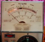
Hi Chris,
A photo I *can* do! (See attachment)
smiles,
Gregg
Attachments
Hi Gregg,
The most important clue you've given was the voltages across the 4R7 resistor. You have almost no voltage (1 V ish vs 7 V) and a high current draw through the resistor (around an amp?!). So there is a possibility of a shorted transistor or filter cap.
I don't see it on the diagram, but there must be an electrolytic cap from B+ to ground. The voltage comes in at 4J (45 R reading on the resistor) and to the circuit (on the 100R reading on your meter).
Looking at your meter face, 100 ohms on the DC 3V scale is about 0.6 VDC, 45 ohms would be just over 1 VDC. If you were on the 5 VDC scale, 100 ohms would be just over 5 V. Got it?
Please measure resistors R404 (680R) and R408 (1K2). One side is ground, the other may have a voltage, let me know. Also measure both sides of R426 (100 R). One side is B+, I want the voltage across this part. I am looking for the shorted part. Also, carefully touch different parts with your finger to see if any are warm. The 4R7 ohm resistor should be warm. Somewhere there is a hot or failed power supply section in your set I think. Could you please e-mail me a picture of the total schematic and sections?
Thanks, Chris
-------------------------------------anatech said:Hi Gregg,
The most important clue you've given was the voltages across the 4R7 resistor. You have almost no voltage (1 V ish vs 7 V) and a high current draw through the resistor (around an amp?!). So there is a possibility of a shorted transistor or filter cap.
I don't see it on the diagram, but there must be an electrolytic cap from B+ to ground. The voltage comes in at 4J (45 R reading on the resistor) and to the circuit (on the 100R reading on your meter).
Looking at your meter face, 100 ohms on the DC 3V scale is about 0.6 VDC, 45 ohms would be just over 1 VDC. If you were on the 5 VDC scale, 100 ohms would be just over 5 V. Got it?
Please measure resistors R404 (680R) and R408 (1K2). One side is ground, the other may have a voltage, let me know. Also measure both sides of R426 (100 R). One side is B+, I want the voltage across this part. I am looking for the shorted part. Also, carefully touch different parts with your finger to see if any are warm. The 4R7 ohm resistor should be warm. Somewhere there is a hot or failed power supply section in your set I think. Could you please e-mail me a picture of the total schematic and sections?
Thanks, Chris
Hi Chris,
Here are the readings:
R404
5 volts across
12.5 volts when tested from chassis ground.
R408
0.9 volts across
0.9 volts when tested from chassis ground.
R426
DEAD volts across
DEAD volts when tested from chassis ground.
R407
0.6 volts across
0.6 volts when tested from chassis ground.
All components cool to the touch. For purposes of comparison I touched components on the other boards. When they are warm, they are *barely* warm. In other words this entire system runs cool because I touched circuits that are definitely working.
I sent you an email in which I advised you to be on the lookout for an email from "Dropload.com." I used them to send you a PDF file I created from photos I took of the schematic. It is a 12MB size file, so I couldn't attach it to an email.
Sincerely,
Gregg
Hi Chris,
I managed to compress that Sansui PDF file I created from 12MB to only 404k by eliminating compatibility with versions of Adobe Acrobat lower than version 5.0. So, if you have version 5.0 or higher you can read this newer compressed version.
It is still too big to attach it here at the site, but I attached it to an email and sent it to you. Please let me know if you got it.
Ps... Those test readings you wanted are posted above this post.
smiles,
-Gregg
- Status
- This old topic is closed. If you want to reopen this topic, contact a moderator using the "Report Post" button.
- Home
- Amplifiers
- Solid State
- Need help with Sansui 5000